
Steel discharger

A technology for steel machines and reclaiming devices, which is applied to metal processing equipment, metal rolling, manufacturing tools, etc., can solve the problems of high pressure on the bottom plate and supporting rollers, complex structure, and multiple driving sources, so as to prolong the service life and simplify the Conveying links, the effect of expanding the size range

Inactive Publication Date: 2020-06-12
XINXING DUCTILE IRON PIPES CO LTD
View PDF5 Cites 0 Cited by
  • Summary
  • Abstract
  • Description
  • Claims
  • Application Information

AI Technical Summary

Problems solved by technology

Although this kind of steel taking machine can achieve the purpose of taking materials from the static beam and discharging them on the roller table, the action of this kind of steel taking machine needs to be controlled by two hydraulic cylinders, which not only has many driving sources, complex structure, and poor control accuracy. , and the overall cost is high
In addition, the kinematic pair between the bottom plate of the lifting beam and the supporting roller is a high pair. Due to the heavy weight of the steel billet, the pressure on the bottom plate and the supporting roller is relatively large, and the wear is serious, resulting in high maintenance frequency and long service life of the equipment.
The traditional steel taking machine needs at least two sets of material shifting mechanisms to complete the two actions of billet dialing in and dialing out. The structure is complex, the equipment cost is high, and the work efficiency is low.
At the same time, the traditional steel taking machine cannot adapt to all sizes of steel billets. When the length of the steel billet exceeds the limit, the steel taking machine needs to be replaced, which directly reduces the working efficiency of the steel taking machine.

Method used


Image

  • Steel discharger
  • Steel discharger
  • Steel discharger

Examples


Embodiment Construction

[0025] Below in conjunction with embodiment the present invention is described in further detail:

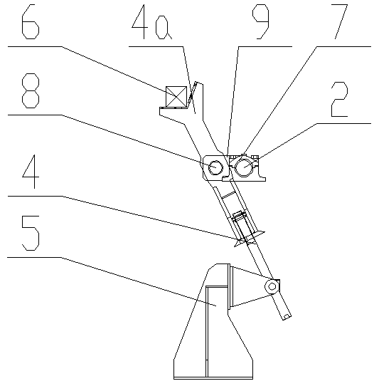
[0026] Such as figure 1 , figure 2 , image 3 As shown, a steel taking machine includes two symmetrical sets of retrieving devices, each set of retrieving devices includes a lever base 5, a lever 4, a reduction motor 1, a long axis 2, a long axis rocker arm 9, and a lever base 5. Long shaft bearing seat 7, motor base 13, motor track 10, bearing seat track 11, base track 12. One end of the driving rod 4 is hinged on the driving rod base 5 , the long axis 2 is driven by the geared motor 1 , the long axis 2 is connected with the geared motor 1 , and the long axis 2 is perpendicular to the driving rod 4 . The long-axis rocker 9 is fixedly connected to the long-axis 2, and the long-axis rocker 9 is perpendicular to the long-axis 2. One end of the long-axis rocker 9 is hinged on the driving lever 4, and the long-axis rocker 9 is connected to the long-axis rocker 9 by a pin 8 at th...


PUM


Abstract

The invention discloses a steel discharger and relates to the technical field of steel rolling auxiliary equipment. The steel discharger comprises at least two discharge devices. Each discharge devicecomprises a deflector rod base, a deflector rod, a reduction motor, a long shaft and a long shaft rocker arm, wherein one end of the deflector rod is hinged to the deflector rod base; the long shaftis driven by the reduction motor and connected with the reduction motor and is perpendicular to the deflector rod; and one end of the long shaft rocker arm is hinged to the deflector rod, and the longshaft rocker arm is fixedly connected to the long shaft and is perpendicular to the long shaft. The two discharge devices are symmetrically arranged. Through the steel discharger, the supporting areafor bearing steel billets is increased, the steel billet conveying link is simplified, and the service life of the steel discharger is prolonged. The steel discharger is simple in structure and stable in operation. The failure rate of equipment is reduced. The adaptability of the steel discharger to different sizes of steel billets is improved.

Description

technical field [0001] The invention relates to the technical field of steel rolling auxiliary equipment, in particular to a steel taking machine. Background technique [0002] In the production workshop of the steel rolling mill, the moving beam on the loading platform moves step by step, and the steel billet is transported to the end of the static beam of the loading platform, and the steel billet automatically slides down to the roller table along the inclined surface of the static beam by its own gravity. However, due to the large vertical distance between the top of the static beam and the surface of the roller table, when the steel billet slides onto the roller table, it will have a great impact on the roller table and side baffles, which greatly shortens the service life of the equipment. [0003] At present, a kind of moving billet steel taking machine commonly used is composed of a lifting hydraulic cylinder and a translation hydraulic cylinder. The lifting hydrauli...

Claims


Application Information

Patent Timeline
Patent Type & Authority Applications(China)
IPC IPC(8): B21B39/02
CPCB21B39/02
Inventor 武东
Owner XINXING DUCTILE IRON PIPES CO LTD
Learn More