
Automatic machining machine for manufacturing steel structure truss through stainless steel pipes

A technology for processing machinery and steel structures, which is applied in the field of automatic processing machinery for making steel structure trusses from stainless steel pipes, and can solve problems such as low efficiency and high labor intensity

Inactive Publication Date: 2020-06-12
吉林省龙聚山钢结构工程有限公司
View PDF7 Cites 5 Cited by
  • Summary
  • Abstract
  • Description
  • Claims
  • Application Information

AI Technical Summary

Problems solved by technology

[0003] The pipe truss structure is mainly composed of main supporting steel pipes and structural steel pipes. The pipe trusses generally need to be manufactured and processed according to the design in advance, and then transported to the construction site for welding and assembly; in order to ensure the reliability of the welding between the structural steel pipes and the main supporting steel pipes Generally, two methods are used for processing, one of which is to cut the end of the structural steel pipe into a contour structure that engages with the main support steel pipe, and the other is to drill holes for the main support steel pipe. Then insert the structural steel pipe into the hole before welding; in the second processing method, the inserted steel pipe should be against the drilled hole, so the end of the inserted steel pipe needs to be processed in advance, that is, the two ends of the steel pipe The end is flattened into a certain taper. The diameter of the steel pipe itself must be larger than the size of the drilled hole to be inserted, so it can be pressed after insertion. In the actual processing process, the two ends of the steel pipe are basically processed manually. The processing efficiency is low, and the long-term manual operation is obviously labor-intensive

Method used


Image

  • Automatic machining machine for manufacturing steel structure truss through stainless steel pipes
  • Automatic machining machine for manufacturing steel structure truss through stainless steel pipes
  • Automatic machining machine for manufacturing steel structure truss through stainless steel pipes

Examples


Embodiment Construction

[0023] The specific embodiment of the present invention will be described in further detail by describing the embodiments below with reference to the accompanying drawings, the purpose is to help those skilled in the art to have a more complete, accurate and in-depth understanding of the concept and technical solutions of the present invention, and To facilitate its practice, but not as a limitation of the invention.

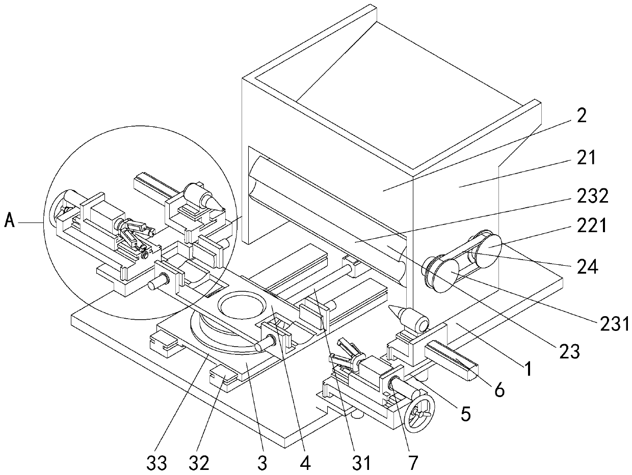
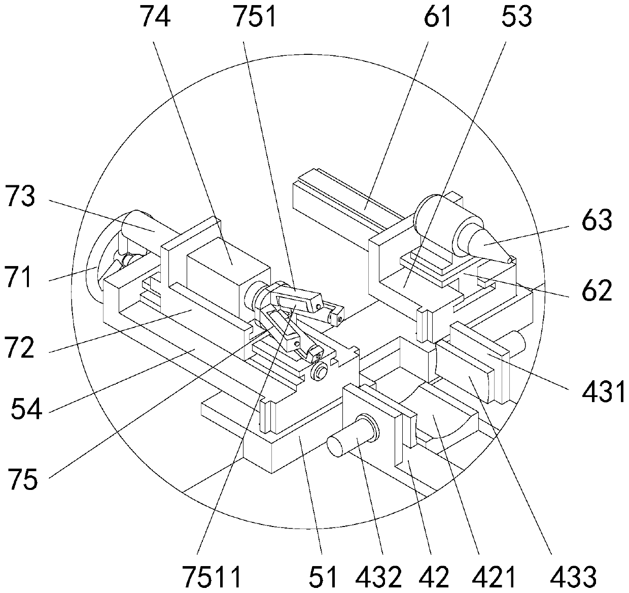
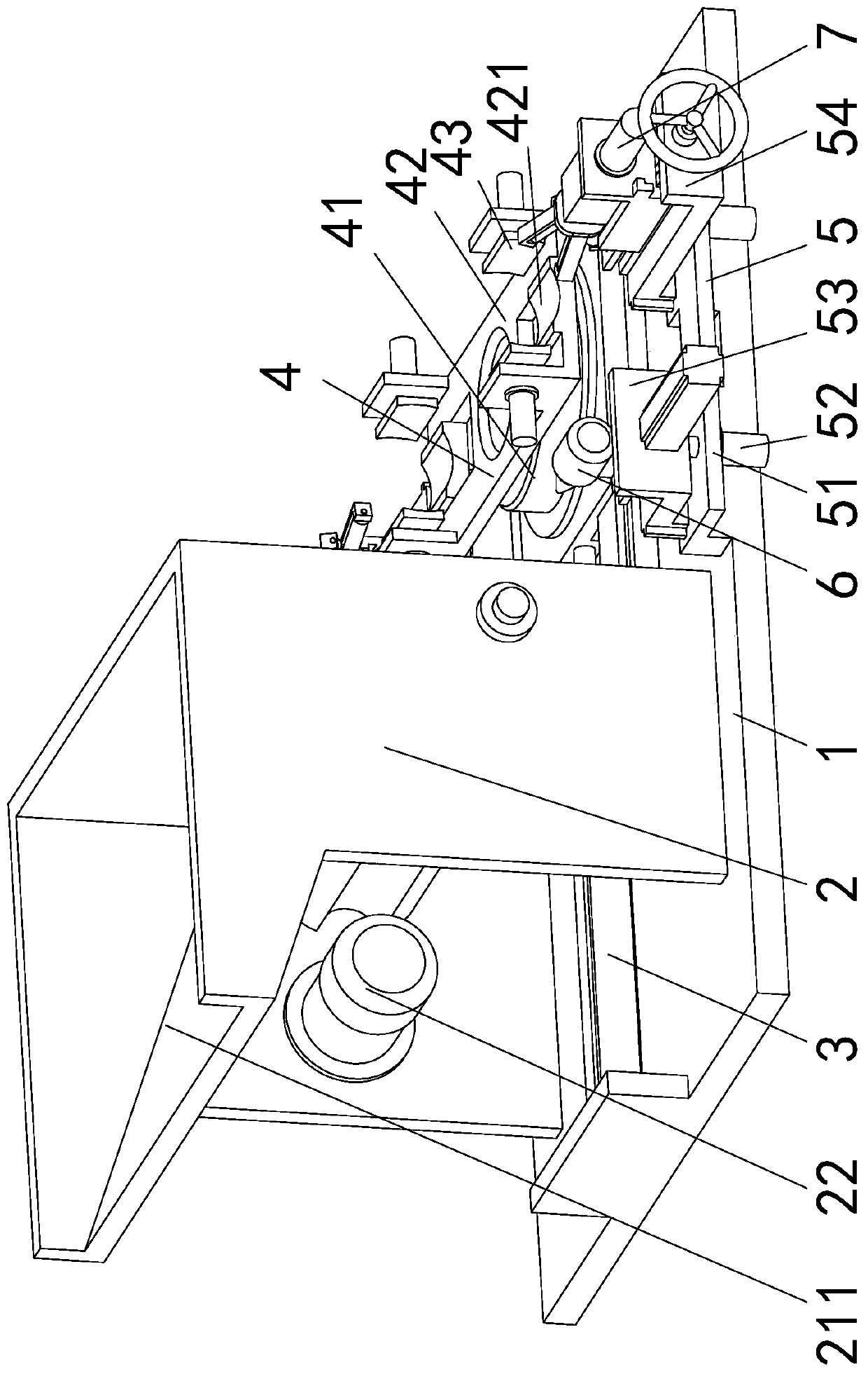
[0024] See attached Figure 1-5As shown, an automatic processing machine for making steel structure trusses from stainless steel pipes, including a base 1, an automatic feeding mechanism 2 arranged on the base 1, a displacement mechanism 3 arranged on the base 1, and a displacement mechanism 3 arranged on the displacement mechanism 3 for supporting Clamping support platform 4 for clamping steel pipe, two mirror images are arranged on the fine-tuning mechanism 5 fixedly installed on the base 1, two centering mechanisms 6 and two mirror-image-set correcting mechan...


PUM


Abstract

The invention relates to an automatic machining machine for manufacturing a steel structure truss through stainless steel pipes. The automatic machining machine comprises a base, an automatic feedingmechanism arranged on the base, a displacement mechanism arranged on the base, a clamping bearing table arranged on the displacement mechanism and used for bearing and clamping a steel pipe, two fineadjustment mechanisms fixedly installed on the base in a mirror image arrangement mode, two centering mechanisms and two correction mechanisms arranged in a mirror image arrangement mode. According tothe machine, through mutual cooperation of the automatic feeding mechanism, the displacement mechanism, the clamping bearing table, the fine adjustment mechanism, the centering mechanisms and the correcting mechanisms, complete automatic machining operation can be achieved, synchronous forming machining of the two ends of the steel pipe can be achieved, the automation degree is high, and comparedwith a traditional semi-automatic manual machining mode, the efficiency is greatly improved, and the labor intensity is greatly reduced.

Description

technical field [0001] The invention relates to the technical field of steel structure processing, and specifically provides an automatic processing machine for manufacturing steel structure trusses from stainless steel pipes. Background technique [0002] Truss refers to a lattice structure composed of rods connected to each other at the ends, and tube truss means that the rods in the structure are all round pipe rods. The trusses make the truss structure economical in materials and light in weight, and are easy to form various shapes to suit different purposes, such as simply supported trusses, arches, frames and towers. In recent years, with the continuous growth of my country's steel production, pipe trusses are being used more and more widely, accounting for an increasing proportion of buildings, industrial plants, automobiles and other industry equipment platform production lines, logistics warehousing, public buildings Gymnasiums, business clubs, high-speed rail platf...

Claims


Application Information

Patent Timeline
IPC IPC(8): B21D41/04B21D43/00B21D43/14
CPCB21D41/04B21D43/003B21D43/006B21D43/145
Inventor 潘岳燕熊芳
Owner 吉林省龙聚山钢结构工程有限公司
Learn More