
Steel pipe chamfering machine

A technology of chamfering machine and steel pipe, which is applied in the direction of metal processing machinery parts, manufacturing tools, positioning devices, etc., which can solve the problems of processing, low material removal rate, and high labor intensity, and achieve large processing range, low cost, and easy loading and unloading of workpieces. convenient effect

Inactive Publication Date: 2020-06-12
SHANDONG UNIV
View PDF9 Cites 2 Cited by
  • Summary
  • Abstract
  • Description
  • Claims
  • Application Information

AI Technical Summary

Problems solved by technology

However, for steel pipes with large diameter or super long length, they cannot be processed on the lathe due to the size limitation of the lathe. Only manual grinding wheel grinding can be used to achieve cutting and internal and external round chamfering. This method has a low material removal rate. , high labor intensity

Method used


Image

  • Steel pipe chamfering machine
  • Steel pipe chamfering machine
  • Steel pipe chamfering machine

Examples


Embodiment Construction

[0021] It should be noted that the following detailed description is exemplary and intended to provide further explanation of the present invention. Unless defined otherwise, all technical and scientific terms used herein have the same meaning as commonly understood by one of ordinary skill in the art to which this invention belongs.

[0022] It should be noted that the terminology used here is only for describing specific embodiments, and is not intended to limit exemplary embodiments according to the present invention. As used herein, unless the invention clearly states otherwise, the singular form is also intended to include the plural form. In addition, it should also be understood that when the terms "comprising" and / or "comprising" are used in this specification, their Indicate the presence of features, steps, operations, means, components and / or combinations thereof;

[0023] For the convenience of description, if the words "up", "down", "left" and "right" appear in th...


PUM


Abstract

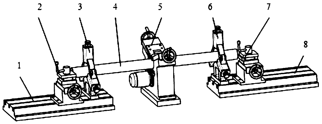
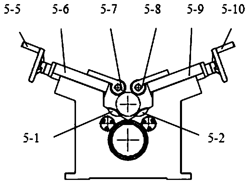
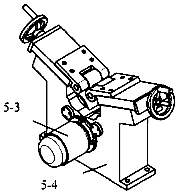
The invention discloses a steel pipe chamfering machine. The steel pipe chamfering machine comprises two knife rests, two central frames and a power device, wherein the two knife rests are used for machining one end or two ends of a steel pipe; the two central frames are positioned at the two ends of the steel pipe and used for supporting the steel pipe and increasing the rigidity of a system; andthe power device is arranged between the two central frames and comprises a motor, two driving wheels, two upper pressing wheels and a driving device. The motor drives the two driving wheels to rotate through a transmission device, and the driving wheels are used for driving the steel pipe to rotate; the upper pressing wheels press a workpiece; and the two upper pressing wheels are connected withthe driving device, so that the upper pressing wheels are close to and away from the steel pipe.

Description

technical field [0001] The invention belongs to the field of steel pipe processing, and in particular relates to a steel pipe chamfering machine. Background technique [0002] As structural components, steel pipes are sometimes welded together with other parts. In order to ensure welding strength, sealing, etc., it is usually necessary to process flat end faces, chamfer inner corners or outer corners, and these processes are generally completed on a general-purpose lathe. However, for steel pipes with large diameter or super long length, they cannot be processed on the lathe due to the size limitation of the lathe. Only manual grinding wheel grinding can be used to achieve cutting and internal and external round chamfering. This method has a low material removal rate. , High labor intensity. Contents of the invention [0003] In order to solve the above-mentioned problems or other potential technical problems existing in the prior art, the present invention discloses a s...

Claims


Application Information

Patent Timeline
Patent Type & Authority Applications(China)
IPC IPC(8): B23B5/16B23Q3/06B23Q1/76
CPCB23B5/16B23B5/167B23Q1/76B23Q3/064
Inventor 尚勇刘健吴涛张柯栾晓娜赵云龙
Owner SHANDONG UNIV
Learn More