Rust removal treatment device for surface of disc-type metal casting

A metal casting and processor technology, which is applied to metal processing equipment, grinding workpiece supports, grinding machine parts, etc., can solve the problems of general effect, low safety factor, and high physical energy consumption of operators, and achieves improved stability. , The effect of improving the degree of tightness and improving the quality of processing

Active Publication Date: 2020-06-12
济南市平阴鑫森有限责任公司
View PDF5 Cites 4 Cited by
  • Summary
  • Abstract
  • Description
  • Claims
  • Application Information

AI Technical Summary

Problems solved by technology

[0003] The traditional derusting method often adopts manual deburring and grinding, and the effect is average. It is characterized in that the working environment is harsh, there is more dust, the safety factor is low, the operator consumes a lot of physical energy, and the efficiency of grinding is not very high; the prior art There is also mechanical derusting and grinding of the brake disc. Because the brake disc is generally divided into upper and lower end faces, and one side is convex, that is, one side of the brake disc is a convex disc. During the grinding process, due to the uneven structure of the two sides, If a fixed mechanical grinder is used, it is not convenient to uniformly grind the two sides of the brake disc, and the flexibility of the processing operation is relatively poor; in addition, the casting generally needs to be positioned during the casting process, which is often done in the prior art. The fixture positions the side wall of the casting. The clamping stability of the general fixture needs to be improved, and at the same time, the protection of the end face of the casting during the clamping and positioning process also needs to be improved.

Method used


Image

  • Rust removal treatment device for surface of disc-type metal casting
  • Rust removal treatment device for surface of disc-type metal casting
  • Rust removal treatment device for surface of disc-type metal casting

Examples


Embodiment 1

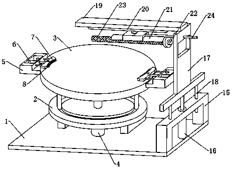
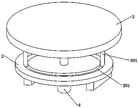
[0035] see Figure 1-2 , a surface derusting processor for disc-type metal castings, comprising a base 1 and a support plate 2 fixedly installed on the upper end of the base 1, the upper end of the support plate 2 is rotatably mounted with a placement plate 3, and the bottom end of the support plate 2 is fixedly installed There is a first rotating motor 4, the telescopic end of the first rotating motor 4 runs through the support plate 2 and is fixedly connected to the middle part of the bottom end of the placement plate 3, and both sides of the bottom end of the placement plate 3 are fixedly connected with guide columns 301, and the support plate 2 The upper end of the upper end is provided with an annular guide groove 201 that matches the two guide columns 301, and the bottom ends of the two guide columns 301 pass through the top of the annular guide groove 201, so balls are fixedly connected thereto, and the balls slide with the inner bottom of the annular guide groove 201 T...


PUM


Abstract

The invention discloses a rust removal treatment device for the surface of a disc-type metal casting and belongs to the technical field of rust removal for castings. According to the rust removal treatment device for the surface of the disc-type metal casting, through cooperation of a pair of casting positioning mechanisms and a polishing roller capable of moving in the up-down and left-right directions, after the disc-type metal casting is positioned, based on different to-be-treated surfaces of the casting, the horizontal position and vertical position of the polishing roller are adjusted toperform targeted treatment on the plane and convex surface of the casting, and the treatment flexibility of the device is effectively improved. An oil seal mechanism capable of being pushed is additionally arranged in the casting positioning mechanism, under pushing of an oil injection piston, the oil seal mechanism makes liquid fat permeate into an oil seal sponge, the oil seal sponge and the outer end wall of the casting form a layer of oil film, and meanwhile the oil seal sponge with some oil not only effectively improves the tightness of adhering to the outer side of the casting, but alsoeffectively achieves a protection function on the casting when clamped.

Description

technical field [0001] The invention relates to the technical field of rust removal for castings, in particular to a surface rust removal processor for disc metal castings. Background technique [0002] The brake disc is an important part of the brake system. It belongs to the disc metal casting. The brake disc is usually formed by stamping. During the production process, the surface is prone to burrs. The existence of these burrs makes the surface of the brake disc It becomes rough and uneven, and when it is used in equipment, it often causes damage such as scratches to the equipment. Therefore, after the stamping of the brake disc is completed, it is necessary to deburr and derust the outer surface of the brake disc. [0003] The traditional derusting method often adopts manual deburring and grinding, and the effect is average. It is characterized in that the working environment is harsh, there is more dust, the safety factor is low, the operator consumes a lot of physica...

Claims


Application Information

Patent Timeline
Patent Type & Authority Applications(China)
IPC IPC(8): B24B1/00B24B27/033B24B41/02B24B41/06B24B47/12B24B47/22B24B55/06
CPCB24B1/00B24B27/033B24B41/02B24B41/06B24B47/12B24B47/22B24B55/06
Inventor 不公告发明人
Owner 济南市平阴鑫森有限责任公司
Why Eureka
Try Eureka