
Liquid nitrogen fracturing process

A process method and liquid nitrogen technology, which are applied in earth-moving drilling, wellbore/well components, and production fluids, etc., can solve the problem of increasing the heat transfer rate between the annulus fluid and the outer wall surface of the fracturing string and the inner wall surface of the casing, which cannot be generated. The problems of low temperature cracking effect and low temperature liquid nitrogen transportation efficiency can improve the overall transformation effect of the reservoir, improve the utilization rate of liquid nitrogen, and improve the reliability of construction.

Inactive Publication Date: 2020-11-27
CHINA UNIV OF PETROLEUM (BEIJING)
View PDF6 Cites 0 Cited by
  • Summary
  • Abstract
  • Description
  • Claims
  • Application Information

AI Technical Summary

Problems solved by technology

After research, it was found that during the fracturing process, the pressure in the well is very high, and nitrogen injection at normal temperature in the annular space will increase the heat exchange rate between the annular fluid and the outer wall of the fracturing string and the inner wall of the casing, which will not only fail to maintain the temperature of the casing, but also cause The fracturing string continuously provides heat, so that the liquid nitrogen continues to absorb heat, and the temperature is very high after being transported to the bottom of the well
Therefore, it can be said that the previously used fracturing method, the delivery efficiency of low-temperature liquid nitrogen is low, and the temperature of liquid nitrogen after delivery to the bottom of the well is too high to produce low-temperature fracturing

Method used


Image

  • Liquid nitrogen fracturing process
  • Liquid nitrogen fracturing process
  • Liquid nitrogen fracturing process

Examples


Embodiment Construction

[0048] The details of the present invention can be understood more clearly with reference to the accompanying drawings and the description of specific embodiments of the present invention. However, the specific embodiments of the present invention described here are only for the purpose of explaining the present invention, and should not be construed as limiting the present invention in any way. Under the teaching of the present invention, the skilled person can conceive any possible modification based on the present invention, and these should be regarded as belonging to the scope of the present invention. It should be noted that when an element is referred to as being “disposed on” another element, it may be directly on the other element or there may also be an intervening element. When an element is referred to as being "connected to" another element, it can be directly connected to the other element or intervening elements may also be present. The terms "mounted", "connec...


PUM


Abstract

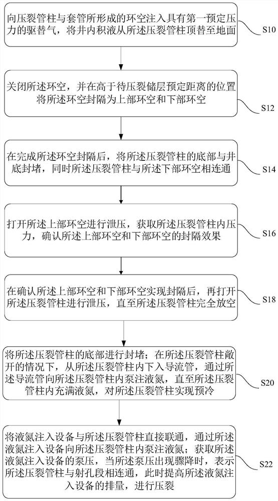
The invention discloses a liquid nitrogen fracturing process method. The method comprises the steps that replacing accumulated fluid in a well to the ground from a fracturing pipe column; at the position higher than a reservoir to be fractured by the reserved distance, packing an annulus into an upper annulus and a lower annulus; blocking the bottom of the fracturing pipe column and the well bottom, and meanwhile enabling the fracturing pipe column to communicate with the lower annulus; opening the upper annulus for pressure relief, obtaining pressure in the fracturing pipe column, and after confirming that the upper annulus and the lower annulus are packed, opening the fracturing pipe column for pressure relief; blocking the bottom of the fracturing pipe column; under the condition of opening the pressuring pipe column, lowering a flow guide pipe from the fracturing pipe column, and pumping and injecting liquid nitrogen into the fracturing pipe column through the flow guide pipe untilthe interior of the fracturing pipe column is full of the liquid nitrogen, and achieving precooling of the fracturing pipe column; communicating a liquid nitrogen injection device with the fracturingpipe column, and pumping and injecting the liquid nitrogen; and when the fracturing pipe column communicates with a perforation segment, increasing the displacement to carry out fracturing. It can beensured that the low-temperature liquid nitrogen has the higher conveying efficiency and better heat preservation effect.

Description

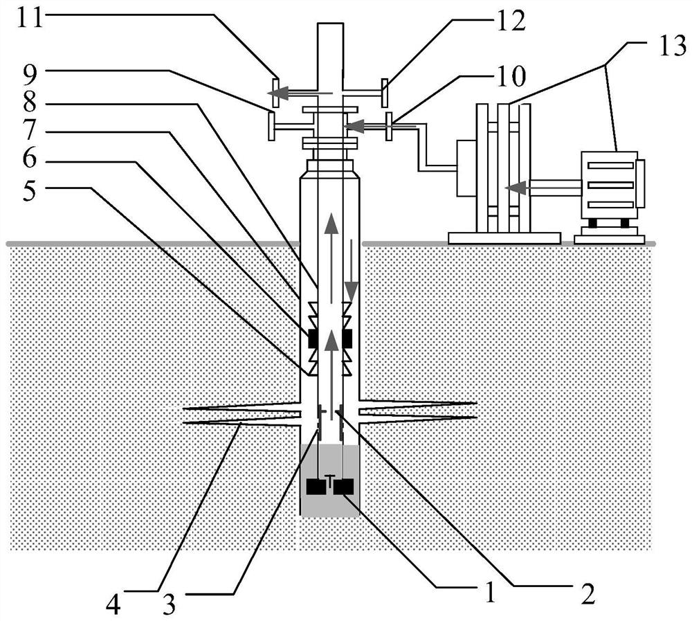
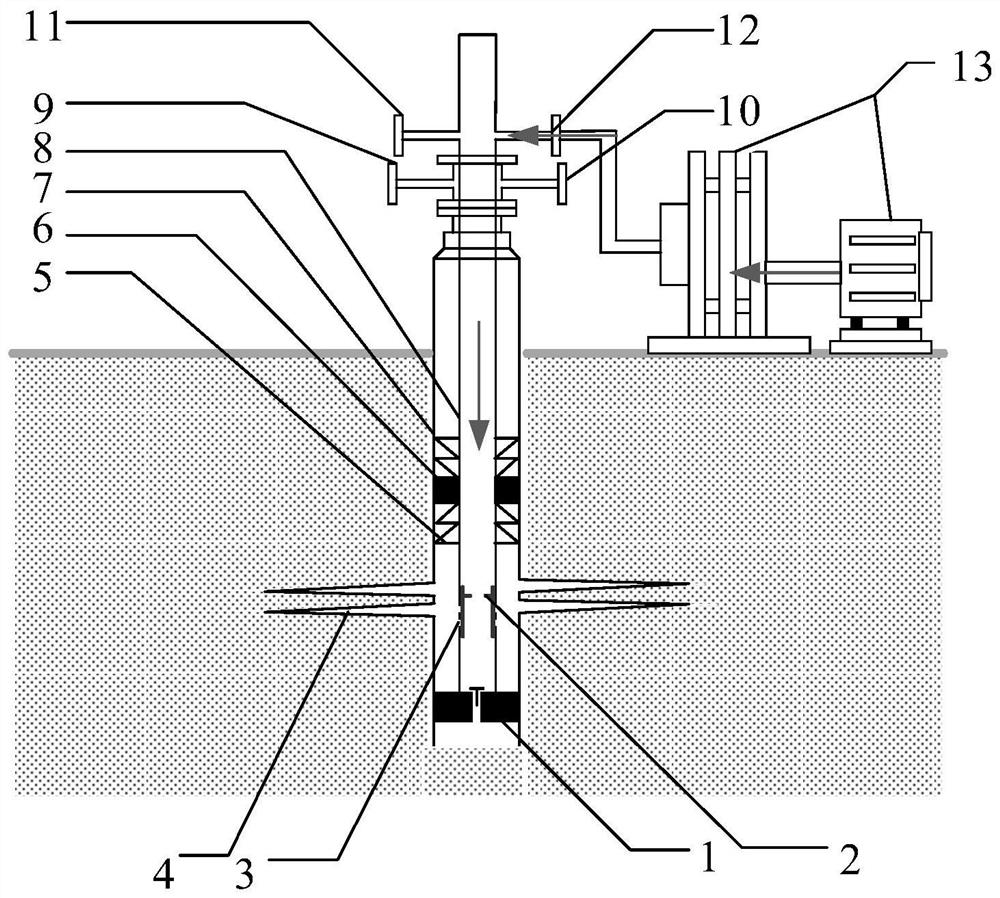
technical field [0001] The invention relates to the technical field of fracturing reconstruction of oil and gas reservoirs, in particular to a liquid nitrogen fracturing process. Background technique [0002] The statements in this section only provide background information related to the present disclosure and may not constitute prior art. [0003] China's unconventional oil and gas resources are huge, among which the recoverable tight gas resources exceed 7×8 12 m 3 , the recoverable resources of shale gas reached 2.5×8 13 m 3 , the total amount of tight oil resources is 124.5×8 7 T. Unconventional oil and gas reservoirs generally have the characteristics of tight lithology, high fracture initiation pressure, and difficult stimulation. Most of the reservoirs need large-scale fracturing to be effectively put into production. On the basis of traditional hydraulic fracturing technology, developing a new reservoir fracturing technology system to reduce the degree of res...

Claims


Application Information

Patent Timeline
Patent Type & Authority Patents(China)
IPC IPC(8): E21B43/26
CPCE21B43/255E21B43/26
Inventor 黄中伟张宏源李欢杨睿月武晓光惠程玉李晓静
Owner CHINA UNIV OF PETROLEUM (BEIJING)
Learn More