Air compressor for compressing air and improving air pressure

A technology of gas pressure and compressed gas, which is applied in the direction of liquid variable displacement machinery, mechanical equipment, machines/engines, etc. It can solve the problems of machine wear, simple structure, and inability to achieve continuous lubrication, and achieve the effect of avoiding waste

Active Publication Date: 2020-06-12
湖南诚跃新能源有限公司
View PDF5 Cites 4 Cited by
  • Summary
  • Abstract
  • Description
  • Claims
  • Application Information

AI Technical Summary

Problems solved by technology

The crankshaft rotates once, the piston reciprocates once, and the process of air intake, compression, and exhaust is realized in the cylinder successively, that is, a working cycle is completed. However, this traditional piston air compressor moves through the crank connecting rod mechanism, so machine loss cannot be avoided. The problem is that this kind of traditional crank-connecting rod has a simple structure and low manufacturing cost, but it needs a lot of lubricating oil for lubrication. Once there is no lubricating oil, it will cause a lot of wear to the machine itself. Due to the use of air compressors, The crank connecting rod structure is located inside the machine body, it will be very inconvenient to add lubricating oil every time, and because the connecting rod structure of the machine is used frequently, it often requires continuous supply of lubricating oil
[0004] Therefore, we propose an air compressor for compressing gas to increase gas pressure, which has the advantage of automatically injecting lubricating oil during hydraulic pressure, and solves the problem of traditional air compressors that are troublesome in filling lubricating oil and cannot achieve continuous lubrication

Method used


Image

  • Air compressor for compressing air and improving air pressure
  • Air compressor for compressing air and improving air pressure
  • Air compressor for compressing air and improving air pressure

Examples


Embodiment Construction

[0031] The following will clearly and completely describe the technical solutions in the embodiments of the present invention with reference to the accompanying drawings in the embodiments of the present invention. Obviously, the described embodiments are only some, not all, embodiments of the present invention. Based on the embodiments of the present invention, all other embodiments obtained by persons of ordinary skill in the art without making creative efforts belong to the protection scope of the present invention.

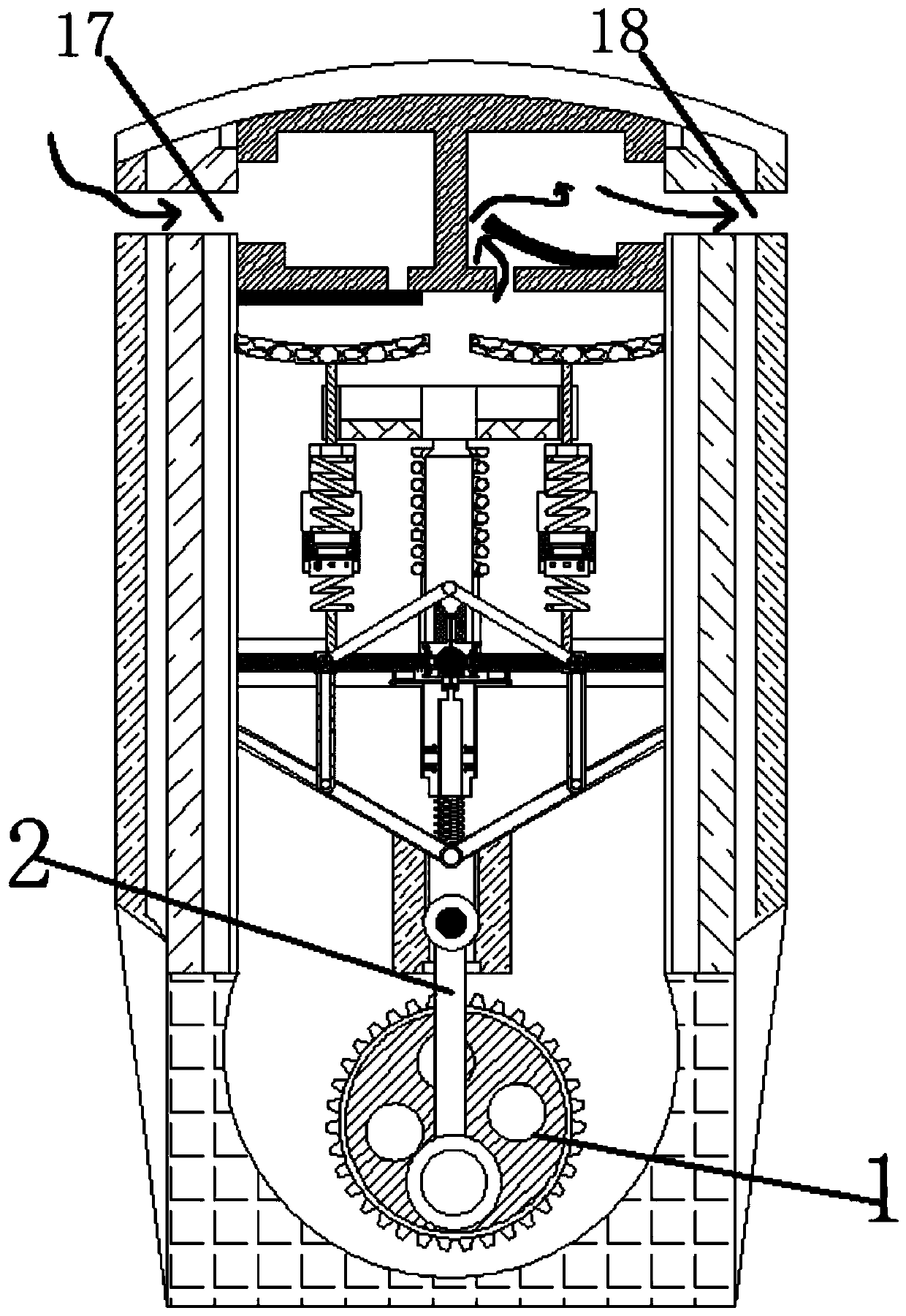
[0032] see Figure 1-12 , an air compressor used to compress gas to increase gas pressure, including a driving gear 1, a connecting rod 2 is movably connected above the driving gear 1, a driving rod 3 is movably installed above the connecting rod 2, and a driving rod 3 is movable above Be connected with moving cross bar-4, the top of moving cross bar-4 is movably installed with telescopic screw rod 5, the top of moving cross bar-4 is movably installed with ins...


PUM


Abstract

The invention relates to the technical field of air compressors, and discloses an air compressor for compressing air and improving air pressure. The air compressor comprises a driving gear, a connecting rod is movably connected above the driving gear, a driving rod is movably mounted above the connecting rod, a pressing spring is movably mounted above a moving cross rod II, a pressing plate is movably connected to the upper portion of the pressing spring, a threaded rod is movably connected into the movable bearing, abutting rubber is movably connected to the left side of the threaded rod, anoil bag is movably connected to the left side of the abutting rubber, and an oil outlet pipe is movably connected to the upper portion of the oil bag. According to the air compressor for compressing the air and improving the air pressure, through the arrangement of the oil bag, the interior of the device can be lubricated without cut-off, the oil bag has resettability, redundant lubricating oil can be adsorbed again to be used next time, and the problems that lubricating oil filling of a traditional air compressor is troublesome, and continuous lubricating cannot be achieved are solved.

Description

technical field [0001] The invention relates to the technical field of air compressors, in particular to an air compressor used to compress gas and increase gas pressure. Background technique [0002] An air compressor is also an air compressor. As the name implies, it can compress air or other gases to high pressure, so as to provide the required power for some tools powered by air or other gases, such as pneumatic wrenches, pneumatic sprayers, etc. Piston air compressors The compressor is the earliest air compressor and the most commonly used air compressor. [0003] Most of the traditional piston air compressor movement mechanism adopts the crank connecting rod mechanism. When the crankshaft rotates, the piston will reciprocate through the transmission of the connecting rod, and the working volume composed of the inner wall of the cylinder, the cylinder head and the top surface of the piston will be cycled. Sexual changes. The crankshaft rotates once, the piston recipro...

Claims


Application Information

Patent Timeline
Patent Type & Authority Applications(China)
IPC IPC(8): F04B39/02
CPCF04B39/0284
Inventor 周明剑何菲菲张翰武
Owner 湖南诚跃新能源有限公司
Why Eureka
Try Eureka