Gear-tooth block meshing switching device for linear reciprocating motion and rotational motion

A technology of reciprocating linear motion and conversion device, applied in the direction of transmission, belt/chain/gear, mechanical equipment, etc., can solve problems such as reducing the explosive expansion pressure of gas, accelerating the wear of cylinder wall, and increasing the resistance of starting and shifting.

Inactive Publication Date: 2012-07-11
安里千
View PDF10 Cites 15 Cited by
  • Summary
  • Abstract
  • Description
  • Claims
  • Application Information

AI Technical Summary

Problems solved by technology

[0005] 2. The swing of the connecting rod in the crankshaft-connecting rod mechanism causes the gas pressure acting on the piston to generate a lateral pressure acting vertically on the cylinder wall, which increases the lateral friction between the piston and the cylinder wall and accelerates the wear of the cylinder wall , which not only reduces the working efficiency of the piston, but also causes the "cylinder" to make the piston unable to work
[0006] 3. Since the top and bottom dead centers of the crankshaft correspond t

Method used


Image

  • Gear-tooth block meshing switching device for linear reciprocating motion and rotational motion
  • Gear-tooth block meshing switching device for linear reciprocating motion and rotational motion
  • Gear-tooth block meshing switching device for linear reciprocating motion and rotational motion

Examples


Embodiment 1

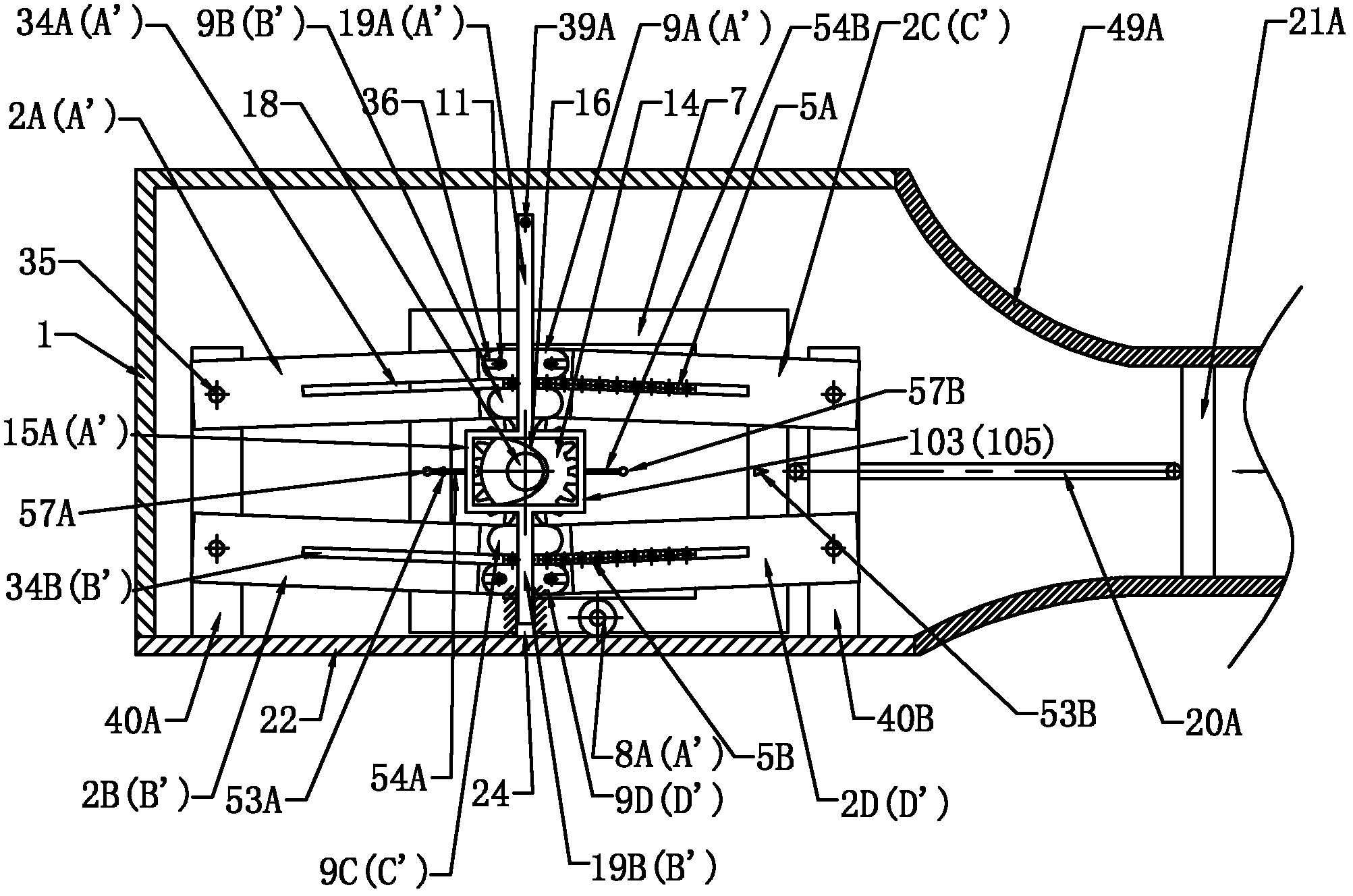
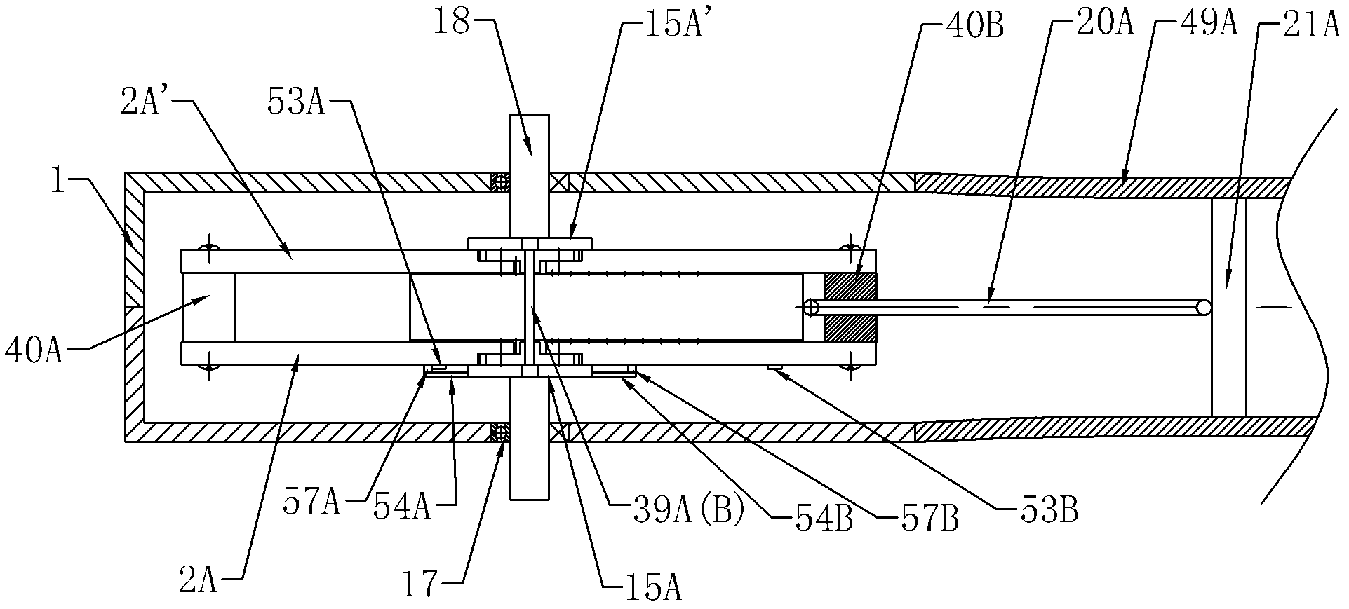
[0062] like Figure 1a , Figure 1b As shown, the reciprocating linear motion and rotary motion conversion device for gear-tooth block engagement of the present invention includes a housing 1, a transmission shaft 18, a gear block mechanism, a tooth block lifting mechanism, a first connecting rod 20A and a first piston 21A, and the gear Both the tooth block mechanism and the tooth block lifting mechanism are located in the housing 1 . Transmission shaft 18 is installed on the front and rear side walls of housing 1 through bearing 17 .

[0063] The gear block mechanism includes a gear 14, an upper tooth block arrangement 5A, a lower tooth block arrangement 5B, a drive frame mechanism 7, a left track plate set and a right track plate set.

[0064] The left track plate group includes the first track plate 2A, the second track plate 2A', the third track plate 2B and the fourth track plate 2B', and the right track plate set includes the fifth track plate 2C, the sixth track plate ...

Embodiment 2

[0095] Embodiment 2 of the reciprocating linear motion and rotary motion conversion device provided by the present invention is different from Embodiment 1 in that:

[0096] like Figure 6a , 6b , 7a, 7b, on the top surface of each tooth block 6 of the upper tooth block arrangement 5A and the first and second end tooth blocks 6A, 6B, an open tooth block groove 37 is opened along the middle line, and on the lower tooth block The bottom surface of each tooth block 6 of the block arrangement 5B and the third and fourth end tooth blocks 6C, 6D defines an open tooth block groove 37 along the midline, and the depth of the tooth block groove 37 is greater than twice the gear tooth height. An upper support rod 38A is installed in the tooth block groove 37 of the upper tooth block arrangement 5A, and a lower support rod 38B is installed in the tooth block groove 37 of the lower tooth block arrangement 5B. The upper support rod 38A and the lower support rod 38B can be positioned at the...

Embodiment 3

[0100] like Figure 8a , Figure 8b As shown, the difference between this embodiment and Embodiment 1 is that: the lifting plate 41 is used instead of the cam to drive the first lifting frame 15A, and the limiting triangular block, the limiting rod and other parts are not provided in this embodiment. bit device. combine Figure 10a , Figure 10b As shown, the lifting pin 44 is set on the rear side of the first lifting rod 19A of the first lifting frame 15A, and the lifting plate 41 is fixedly installed on the upper frame 56A of the drive frame mechanism 7, and the front side of the lifting plate 41 is opened. Oval lift groove 42, lift groove 42 comprises two horizontal straight grooves and arc grooves connecting the two ends of the two horizontal straight grooves, the distance between the centerlines of the horizontal straight grooves is equal to 2 times of the tooth height of gear 14, lift groove 42 The width is equal to the diameter of the lift pin 44, and the lift pin 4...


PUM


Abstract

The invention provides a gear-tooth block meshing switching device for linear reciprocating motion and rotational motion. Four pairs of track plates are mounted in a casing, one ends of the track plates are hinged to the inner walls of the two sides of the casing, the other ends of the track plates are provided with track grooves respectively, and a track shifting mechanism lifter is arranged among the four pairs of track plates. Tooth block lines including a plurality of tooth blocks are mounted on a driving frame mechanism, sliding pins extending from two sides of each tooth block are respective disposed in each track groove, a gear fixedly mounted with a transmission shaft is arranged between the two tooth block lines, and the lifter driving device drives the lifter to lift or descend the track plates. Besides, a frame of the driving frame mechanism is connected with one end of a connecting rod, and the other end of the connecting rod is connected with a piston. The switching device is capable of realizing equivalent switching between linear reciprocating motion and rotational motion.

Description

technical field [0001] The invention relates to a reciprocating linear motion and rotary motion conversion device, in particular to a gear-rack meshing motion conversion device for mutual conversion between linear reciprocating motion and circular motion. Background technique [0002] In mechanical engineering, such as piston engines, compressors and other machines that need to convert between linear reciprocating motion and circular motion, the crankshaft (crank) connecting rod mechanism is generally used at present. [0003] The design and manufacture of the traditional crankshaft (handle) linkage mechanism has been very perfect, but there are obvious shortcomings in both theoretical analysis and practical application: [0004] 1. The conversion efficiency of the crankshaft (handle) linkage mechanism is low. Taking the piston-connecting rod-crankshaft (handle) mechanism engine as an example, the gas explosion pressure of the piston is transmitted to the crankshaft (handle...

Claims


Application Information

Patent Timeline
IPC IPC(8): F16H37/12
Inventor 安里千刘庆毛灵涛安晶
Owner 安里千
Why Eureka
Try Eureka