
Harmonic drive crank rocker arm rotary steering engine

A harmonic drive, rotary technology, applied in the direction of mechanical equipment, aircraft control, aircraft parts, etc., can solve the problems of increasing system error, affecting the accuracy of steering gear, increasing the quality of steering gear, etc., to achieve the increase of steering gear reducer Ratio, realize high-precision transmission, and amplify the effect of steering gear torque

Active Publication Date: 2020-06-12
HUBEI SANJIANG AEROSPACE HONGFENG CONTROL
View PDF6 Cites 1 Cited by
  • Summary
  • Abstract
  • Description
  • Claims
  • Application Information

AI Technical Summary

Problems solved by technology

The traditional electric steering gear is limited by the transmission mode, and it is difficult to output a large torque in a small space
There are two commonly used methods in the prior art. One is to increase the output torque by adopting multi-stage gear transmission, which will increase the system error due to too many transmission links, thus affecting the accuracy of the steering gear.
The second is to adopt the method of increasing the reduction ratio of a certain link, which requires a large installation space and increases the quality of the steering gear, which restricts the miniaturization of equipment such as unmanned aerial vehicles and cruise guidance missiles.
The airborne small-volume and high-torque composite steering gear needs to greatly reduce the volume and mass of the steering gear on the basis of the traditional steering gear, and achieve high torque output, but the existing technology does not meet the needs of small size, light weight and large size. Composite servo structure with torque output

Method used


Image

  • Harmonic drive crank rocker arm rotary steering engine
  • Harmonic drive crank rocker arm rotary steering engine
  • Harmonic drive crank rocker arm rotary steering engine

Examples


Embodiment Construction

[0024] In order to make the objectives, technical solutions and advantages of the present invention clearer, the following further describes the present invention in detail with reference to the accompanying drawings and embodiments. It should be understood that the specific embodiments described here are only used to explain the present invention, but not to limit the present invention. In addition, the technical features involved in the various embodiments of the present invention described below can be combined with each other as long as they do not conflict with each other.

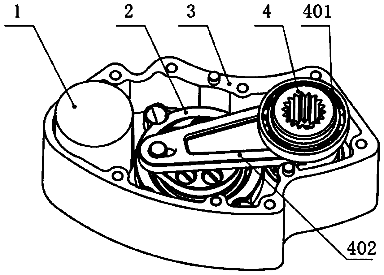
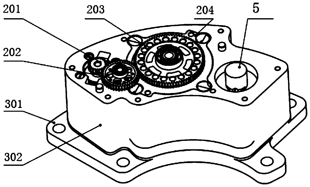
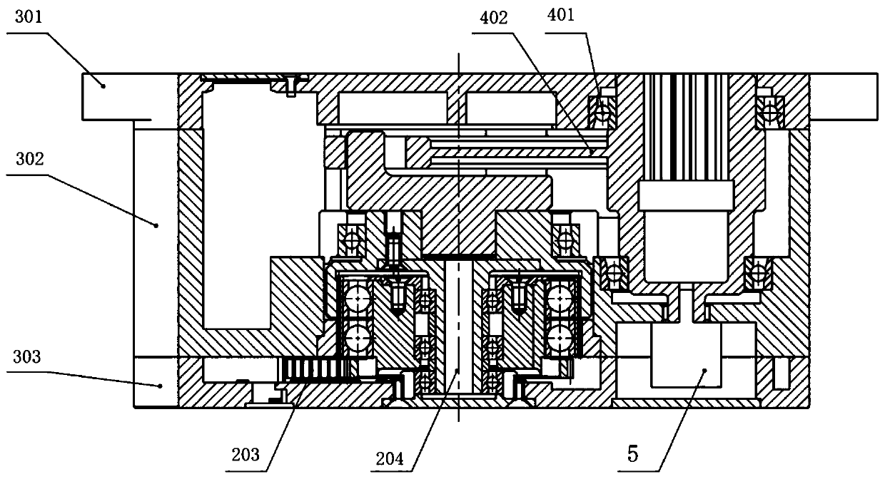
[0025] figure 1 It is a schematic diagram of the structure of the harmonically driven crank arm rotary steering gear in the embodiment of the present invention with the base removed. figure 2 It is a schematic diagram of the structure of the harmonic-driven crank arm rotary steering gear in the embodiment of the present invention with the upper end cover removed. Such as figure 1 with figure 2 As shown...


PUM


Abstract

The invention discloses a harmonic drive crank rocker arm rotary steering engine. The harmonic drive crank rocker arm rotary steering engine comprises a motor (1), an output shaft, an engine body assembly (3), a speed reducing mechanism (2) and a rocker arm output shaft assembly (4). The speed reducing mechanism (2) comprises a harmonic reducer (204), an input gear (201), an intermediate gear (202) and an output gear (203), wherein the input gear (201), the intermediate gear (202) and the output gear (203) are sequentially engaged, the input gear (201) is connected with the motor (1), and thenumber of teeth of the input gear (201), the intermediate gear (202) and the output gear (203) is sequentially increased to form a first-stage reduction unit; the harmonic reducer (204) is connected with the output gear (203) to form a second-stage reduction unit; and the rocker arm output shaft assembly (4) comprises a rocker arm output shaft (402), wherein the rocker arm output shaft (402) is ofa crank-shaped rocker arm structure, one end of the rocker arm output shaft (402) is connected with the speed reducing mechanism (2), and the other end of the rocker arm output shaft (402) is connected with the output shaft. The harmonic drive crank rocker arm rotary steering engine has the advantages of being small in size, light in weight, high in transmission precision and large in output torque.

Description

Technical field [0001] The invention belongs to the technical field of rotary steering gears, and more specifically, relates to a harmonic-driven crank rocker rotary steering gear. Background technique [0002] In recent years, with the continuous progress of basic industrial level and modern technology, the servo system is developing in the direction of miniaturization, long life, high efficiency, and maintenance-free design. Research on technologies such as unmanned aerial vehicles and cruise guided missiles in my country has become one of the current hot spots. Due to the small size of unmanned aerial vehicles and cruise guided missiles, and the extremely high utilization of internal space, the design and development of the steering gear used to adjust their space attitude or engine control is difficult. Harmonic-driven crank-rocker rotary steering gear came into being. Compared with the traditional electric steering gear, it greatly reduces the volume and mass of the steerin...

Claims


Application Information

Patent Timeline
IPC IPC(8): F42B15/00F42B10/66B64C9/00F16H37/12F16H57/023
CPCF42B15/00F42B10/66B64C9/00F16H37/12F16H57/023F16H2057/02034F16H2057/02039F16H2057/02086F16H2057/02091
Inventor 陈子玮王永辉郭常广
Owner HUBEI SANJIANG AEROSPACE HONGFENG CONTROL
Learn More