Automatic line pressure maintaining mechanism

A technology of automatic line and pressure maintaining device, which is applied in the direction of line/collector parts, auxiliary devices, electrical components, etc., can solve the problems of difficult to improve the economic benefits of enterprises, high labor intensity, high labor cost, etc., to save manpower and labor costs , Guarantee the quality of fastening and avoid the effect of too small pressure

Pending Publication Date: 2020-06-12
ALLEGRO TECH
View PDF0 Cites 3 Cited by
  • Summary
  • Abstract
  • Description
  • Claims
  • Application Information

AI Technical Summary

Problems solved by technology

[0002] There is a BTB connector on the small PCB inside the mobile phone. The BTB connector includes a BTB connector and a BTB connector. The BTB connector is welded on the small PCB, and the BTB connector is buckled on the BTB connector. In order to ensure the fastening quality of the connector and the BTB connector, it is necessary to perform a pressure-holding process on the BTB connector and the BTB connector that have been fastened. In the prior art, the pressure-holding process is generally performed manually. Take out the board, then place the small PCB board on the positioning slot of the carrier plate, and finally apply downward pressure on the BTB connector and keep the pressure for a certain period of time to complete the pressure holding process. The disadvantages in this process are: 1 1. Manpower operation is required for a long time, and the labor intensity is high; 2. The pressure exerted by workers on the BTB connector is difficult to control. When the pressure is too large, it is easy to cause damage to the product. The fastening quality of the connecting seat; 3. The labor cost is high, and it is difficult to improve the economic benefits of the enterprise

Method used


Image

  • Automatic line pressure maintaining mechanism
  • Automatic line pressure maintaining mechanism
  • Automatic line pressure maintaining mechanism

Examples


Embodiment Construction

[0024] The present invention will be further described below in conjunction with accompanying drawing:

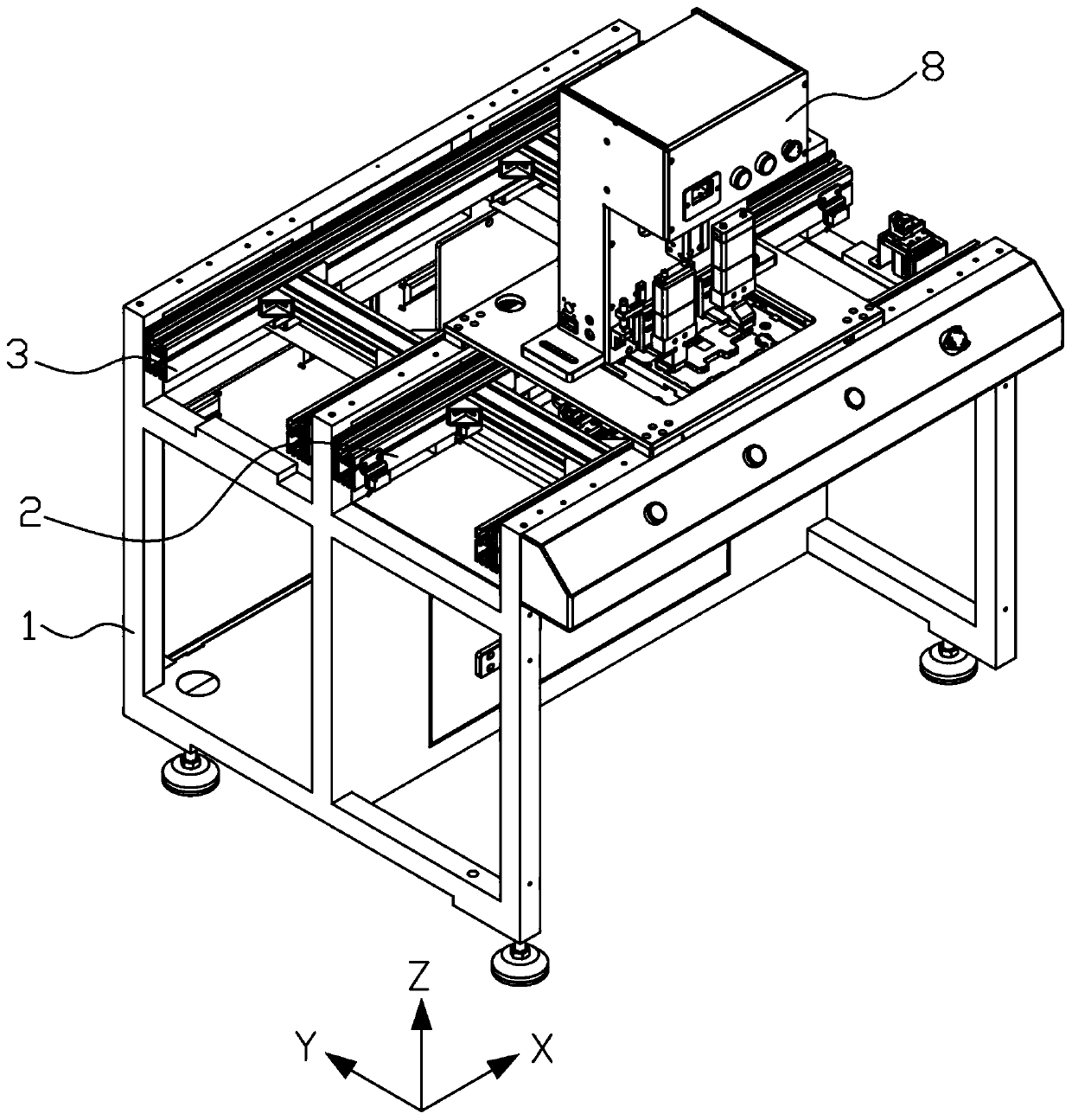
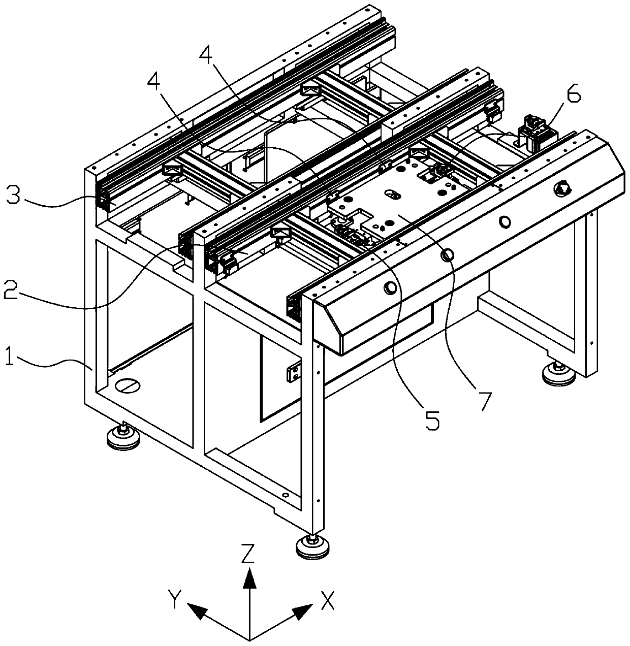
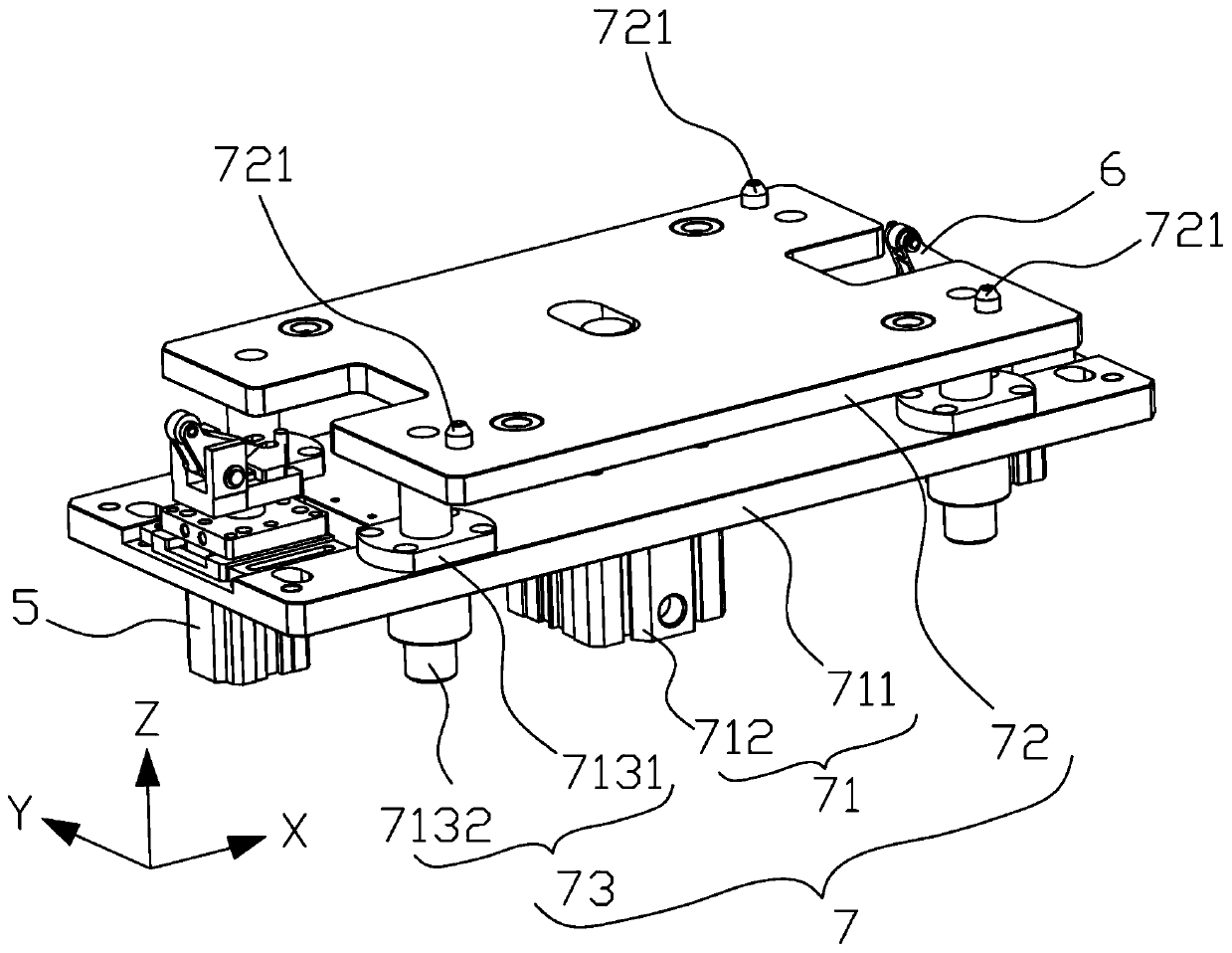
[0025] Please refer to Figure 1 to Figure 3 , an automatic line pressure maintaining mechanism, including a frame 1, a feeding conveyor belt 2, a return conveyor belt 3, a carrier sensor 4, a blocking device one 5, a blocking device two 6, a carrier positioning device 7 and a pressure maintaining device 8 , the feeding conveyor belt 2 and the return conveyor belt 3 are respectively fixed in the front and rear of the top of the frame 1 and are all lower than the frame 1, the blocking device one 5, the tray positioning device 7 and the blocking device two 6 along the X Axially arranged successively in the feeding conveyor belt 2, the carrier sensor 4 is fixedly connected to the inner wall of the feeding conveyor belt 2 and is located between the blocking device one 5 and the blocking device two 6, the blocking device one 5 and the blocking device two 6 are respectively fixe...


PUM


Abstract

The invention provides an automatic line pressure maintaining mechanism. The mechanism comprises a rack, a feeding conveying belt, a backflow conveying belt, a carrying disc sensor, a first blocking device, a second blocking device, a carrying disc positioning device and a pressure maintaining device. The feeding conveying belt and the backflow conveying belt are fixedly arranged in the front portion and the rear portion of the top of the rack respectively. The first blocking device, the carrying disc positioning device and the second blocking device are sequentially arranged in the feeding conveying belt in the X-axis direction. The loading tray sensor is fixedly connected with the feeding conveying belt and located between the first blocking device and the second blocking device. The first blocking device and the second blocking device are fixedly arranged on the two sides of the loading tray positioning device in the X-axis direction respectively, the loading tray positioning deviceis fixedly connected with the feeding conveying belt, and the pressure maintaining device is fixedly arranged on the rack and located over the loading tray positioning device. According to the invention, the buckling quality of the BTB connector and the BTB connecting seat can be ensured, and the BTB connector and the BTB connecting seat can be connected to an automatic mobile phone production line, so that the manpower and the labor cost are saved to the maximum extent.

Description

technical field [0001] The invention relates to the field of mobile phone manufacturing, in particular to an automatic line pressure maintaining mechanism. Background technique [0002] There is a BTB connector on the small PCB inside the mobile phone. The BTB connector includes a BTB connector and a BTB connector. The BTB connector is welded on the small PCB, and the BTB connector is buckled on the BTB connector. In order to ensure the fastening quality of the connector and the BTB connector, it is necessary to perform a pressure-holding process on the BTB connector and the BTB connector that have been fastened. In the prior art, the pressure-holding process is generally performed manually. Take out the board, then place the small PCB board on the positioning slot of the carrier plate, and finally apply downward pressure on the BTB connector and keep the pressure for a certain period of time to complete the pressure holding process. The disadvantages in this process are: 1 ...

Claims


Application Information

Patent Timeline
IPC IPC(8): H05K3/34H01R43/02B23K3/08
CPCB23K3/08B23K3/087H01R43/0256H05K3/34
Inventor 李志勋李旭辉
Owner ALLEGRO TECH
Why Eureka
Try Eureka