Connecting structure, rack and aircraft

A connecting structure and connecting part technology, which is applied in the field of aircraft, can solve the problems of increasing the volume of the whole machine, poor vibration damping effect, and increased difficulty in setting up the vibration damping system, so as to reduce the impact of vibration, solve the problem of fuselage vibration, Improve the effect of vibration reduction effect

Pending Publication Date: 2020-06-12
SZ DJI TECH CO LTD
View PDF0 Cites 2 Cited by
  • Summary
  • Abstract
  • Description
  • Claims
  • Application Information

AI Technical Summary

Problems solved by technology

[0003] In the prior art, the vibration impact of the fuselage is reduced by adding a vibration reduction system between the fuselage and the arm. However, in many cases, aircraft such as drones have volume requirements, and the addition of a vibration reduction system will undoubtedly

Method used


Image

  • Connecting structure, rack and aircraft
  • Connecting structure, rack and aircraft
  • Connecting structure, rack and aircraft

Examples


Example Embodiment

[0053] Example 1:

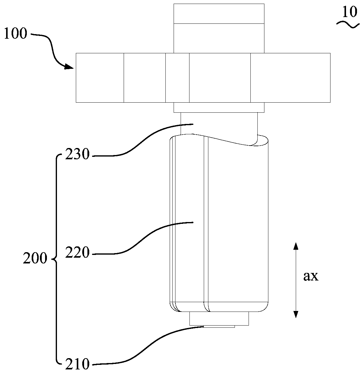
[0054] like image 3 As shown, in addition to the features in any of the above embodiments, the rotating shaft assembly 200 is further defined to include: a rotating shaft 210 and a rotating member 220, wherein the rotating shaft 210 is connected with the elastic body 100; the rotating member 220 is provided on the rotating shaft 210 and can be wound around The rotating shaft 210 rotates, the rotating member 220 is used to connect with the other one of the arm 20 and the body 30, and the rotating member 220 and the elastic body 100 are in driving cooperation; wherein, the rotating member 220 rotates to make the arm 20 close During the process of the third position, the elastic body 100 is compressed. When the rotating member 220 rotates to make the arm 20 exceed the third position, the elastic body 100 is released, and the elastic restoring force generated by the elastic body 100 makes the rotating member 220 drive the motor The arm 20 is rotated to the fi...

Example Embodiment

[0056] Example 2:

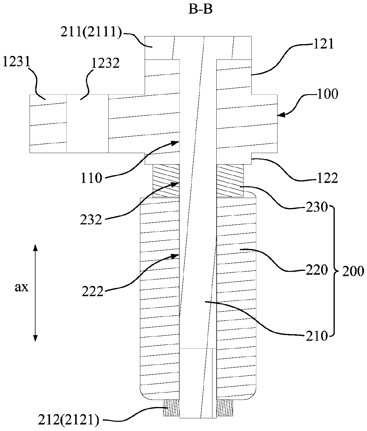
[0057] like image 3 As shown, in addition to the features of the above-mentioned Embodiment 1, it is further limited that: the elastic body 100 is provided with an elastic body shaft hole 110 , and a part of the rotating shaft 210 is sleeved in the elastic body shaft hole 110 . A shaft hole is formed between the elastic body 100 and the rotating shaft 210, so that the elastic body 100 can efficiently absorb the vibration at any radial position of the rotating shaft 210. In this way, the entire connecting structure 10 not only presses or releases the elastic body 100 to store energy or The direction of the energy release can have better flexibility (it can also be said that the stiffness is smaller), and the entire connecting structure 10 also has better flexibility in any radial direction of the rotating shaft 210, so that the connecting structure 10 is connected between the arm 20 and the fuselage. The vibration reduction effect between 30 is better, whi...

Example Embodiment

[0066] Example 3:

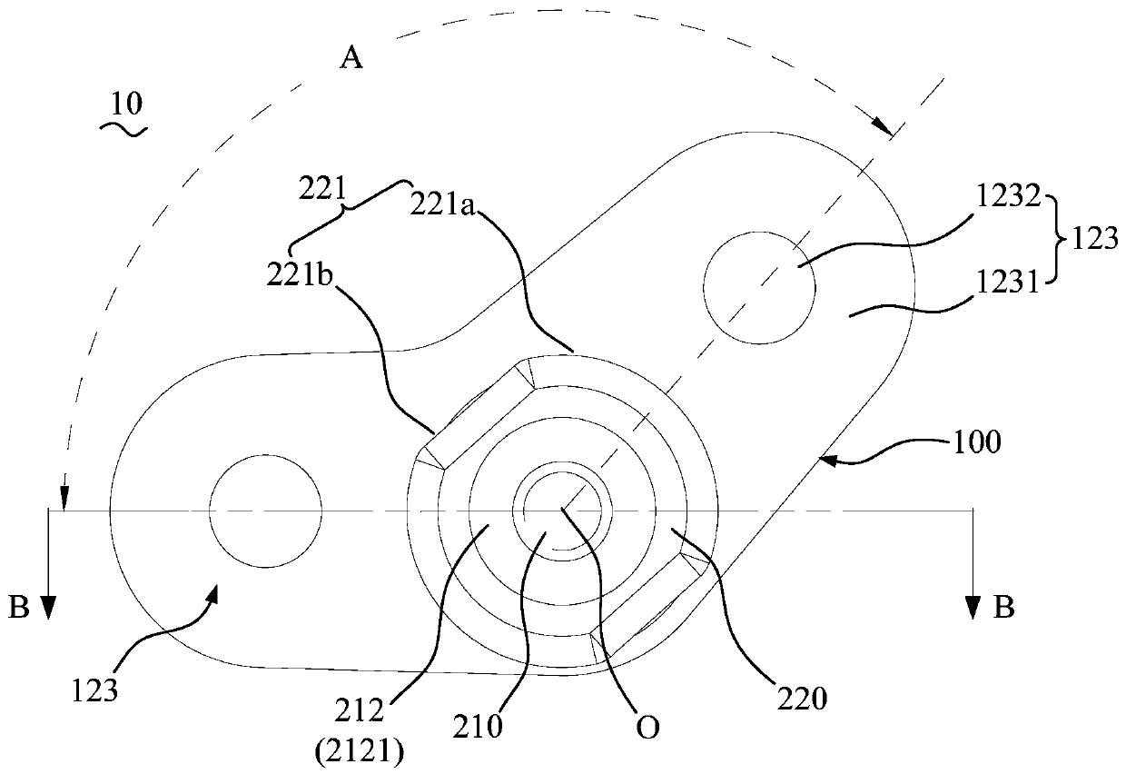
[0067] like Figure 4 As shown, in addition to the features of any of the above-mentioned embodiments, it is further limited that: the rotating shaft 210 is provided with a first stopper portion 211 and a second stopper portion 212, and the first stopper portion 211 and the second stopper portion 212 are distributed at intervals along the axial direction of the rotating shaft 210, and the part of the rotating shaft 210 located between the first stop part 211 and the second stop part 212 is connected to the elastic body 100 and the rotating part 220, so that the elastic body 100 and the rotating part 220 It is axially restricted between the first stop portion 211 and the second stop portion 212 .

[0068]In this solution, the first stopper 211 and the second stopper 212 are arranged to be distributed on both sides of the elastic body 100 and the rotating member 220 along the axial direction of the rotating shaft 210 , so that the axial direction of the elas...


PUM


Abstract

A connection structure includes: an elastic body (100) for connecting to one of an arm (20) and a fuselage (30); the rotating shaft assembly (200) is connected with the elastic body (100) and used forbeing connected with the other one of the vehicle arm (20) and the vehicle body (30), so that the vehicle arm (20) rotates relative to the vehicle body (30) to form at least one stroke interval; wherein the stroke interval is provided with a first position, a second position and a third position located between the first position and the second position, and the rotating shaft assembly (200) is further used for abutting against and compressing the elastic body (100) in the process that the vehicle arm (20) gets close to the third position. The elastic body (100) is also used for enabling thevehicle arm (20) to automatically rotate to the first position or the second position when the vehicle arm (20) exceeds the third position; the invention also relates to a frame and an aircraft.

Description

technical field [0001] The present application relates to the technical field of aircraft vibration-damping connection, in particular, to a connection structure, a frame and an aircraft. Background technique [0002] For aircraft such as drones, the power system is the main source of fuselage vibration, and the vibration of the fuselage will cause many problems, such as IMU overrange, aliasing, structural fatigue, etc. [0003] In the prior art, the vibration impact of the fuselage is reduced by adding a vibration reduction system between the fuselage and the arm. However, in many cases, aircraft such as drones have volume requirements, and the addition of a vibration reduction system will undoubtedly increase the The size of the whole machine, and the need to realize both the rotation function and the self-locking function between the existing fuselage and the arm, which makes it more difficult to set up the vibration reduction system, and the vibration reduction effect is ...

Claims


Application Information

Patent Timeline
IPC IPC(8): B64C1/06F16F15/08
CPCB64C1/069F16F15/08
Inventor 蒋李吴利鑫陈志强
Owner SZ DJI TECH CO LTD
Why Eureka
Try Eureka