
Method and device for determining the travel of a clutch or a gear actuator in a hydraulic clutch actuation system or a hydraulic gear actuation system

A hydraulic clutch and operating system technology, applied in clutches, fluid-driven clutches, non-mechanical-driven clutches, etc., can solve the problems of complex structure and space of sound signals, and achieve the effect of suppressing temperature expansion

Active Publication Date: 2020-06-12
SCHAEFFLER TECH AG & CO KG
View PDF9 Cites 0 Cited by
  • Summary
  • Abstract
  • Description
  • Claims
  • Application Information

AI Technical Summary

Problems solved by technology

However, the sound signal generation on the driven side is relatively complex and requires additional installation space in the area of ​​the clutch actuating system

Method used


Image

  • Method and device for determining the travel of a clutch or a gear actuator in a hydraulic clutch actuation system or a hydraulic gear actuation system

Examples


Embodiment Construction

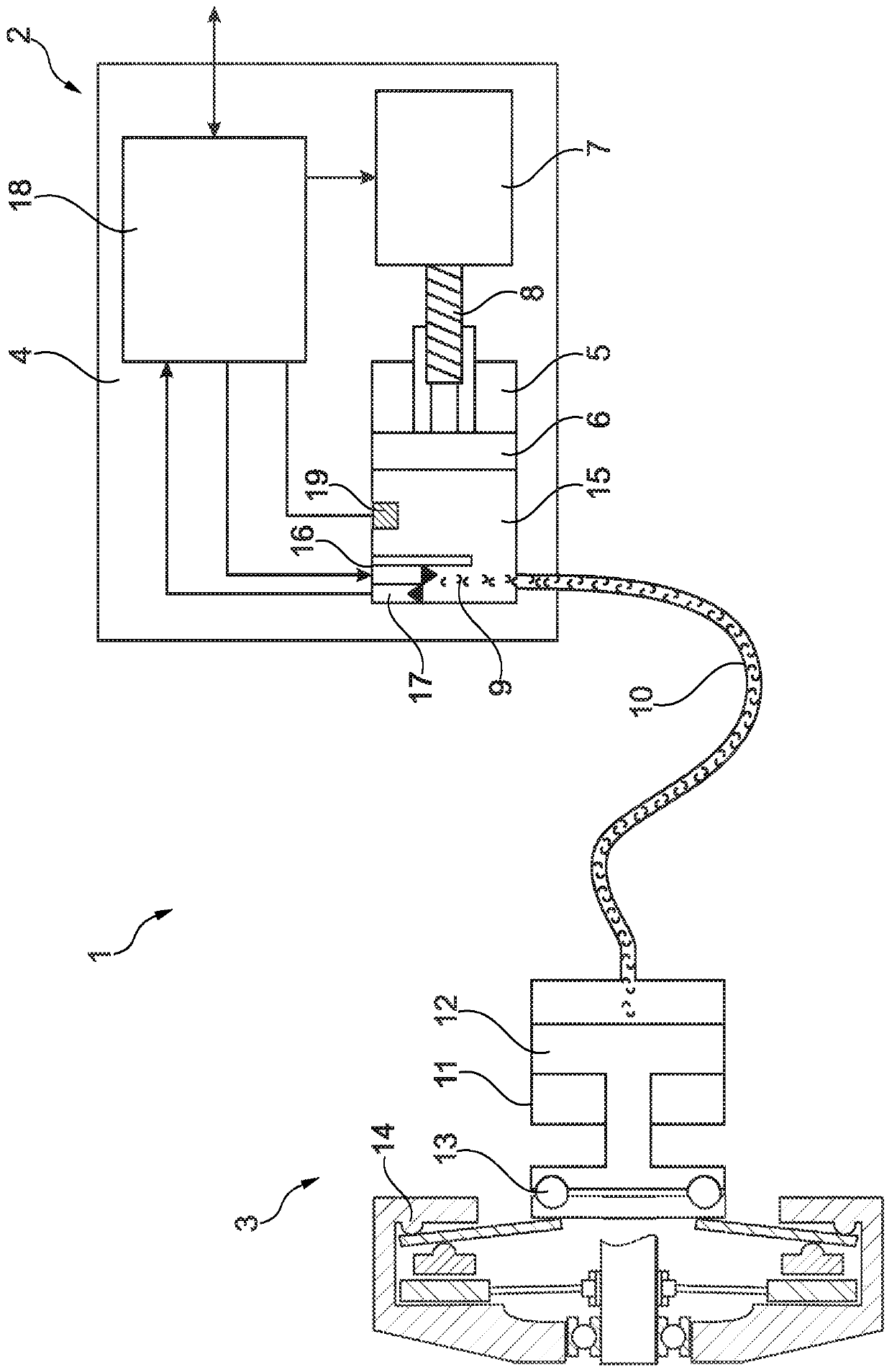
[0021] in figure 1 An embodiment of the device according to the invention is shown in, which is used in a clutch operating system 1 for example in a motor vehicle. The clutch operating system 1 includes a driving side 2 and a driven side 3. The active side 2 has a clutch actuator 4 which includes a master cylinder 5. The active piston 6 arranged in the active cylinder 5 is driven by an electric motor 7, wherein the rotational movement of the electric motor 7 is transformed into a linear movement of the active piston 6 of the active cylinder 5 via the screw 8. The master cylinder 5 is connected to the slave cylinder 11 on the driven side 3 via a hydraulic section 10 filled with hydraulic fluid 9. The slave cylinder has a slave piston 12. The volume of the hydraulic fluid 9 in the hydraulic section 10 of the slave piston is determined by the master When the piston 6 is squeezed, the clutch 14 is operated via the release bearing 13.

[0022] A sound transmitting unit 16 and a soun...


PUM


Abstract

The invention relates to a method for determining the travel of a clutch in a hydraulic clutch actuation system, in which a hydraulic fluid (9) extending between a transmitting end (2) and a receivingend (3) is subjected to an acoustic signal in order to generate a wave packet. In a method which makes it possible to reliably determine the release travel of the clutch with simple means, the acoustic signal is fed into the hydraulic fluid at the transmitting end (2) of the clutch actuation system (1), wherein a wave packet generated by the acoustic signal is reflected back at the receiving end(3) toward the transmitting end (2) and, at said transmitting end (2), a transit time ([delta]t) of the transmitted and reflected wave packet is evaluated in order to determine the travel (D) of the clutch.

Description

Technical field [0001] The invention relates to a method for determining the stroke of a clutch in a hydraulic clutch operating system and a device for implementing the method, in which a sound signal is applied to the hydraulic fluid extending between the driving side and the driven side . Background technique [0002] From DE 10 2012 218 255 A1, a method for operating a clutch is known, which has a hydrostatic actuator which includes a drive screw that rotates so that the piston of the active cylinder Movement in the axial direction, wherein the stroke of the piston is calculated by means of at least one sensor unit. For this reason, a stroke detector is configured to the piston to compare the actual stroke with the calculated stroke. The stroke of the piston can be determined by means of a pressure sensor or a stroke sensor device. The disadvantage here is that the clutch engagement stroke is determined via the actuator stroke, which is an indirect measurement. Although th...

Claims


Application Information

Patent Timeline
Patent Type & Authority Applications(China)
IPC IPC(8): F16D48/00F16D48/02
CPCF16D25/08F16D48/00F16D48/02F16D48/06F16D2500/1024F16D2500/10412F16D2500/1045F16D2500/3024F16D2500/3026F16D2500/3056F16D2500/30803F16D2500/3166F16D2500/50245F16D2500/5102F16D2500/7041F16D2500/7103F16D2500/7109G01H3/00F16D48/066F16D2500/1026
Inventor 埃哈德·侯德路思拉斐尔·克伦齐格
Owner SCHAEFFLER TECH AG & CO KG
Learn More