Nail taking device for orthopedics

An orthopaedic, sliding installation technology, applied in medical science, surgery, fixator and other directions, can solve the problems of screw falling, uneven screw force, easy slippage, etc., to achieve the effect of convenient screw removal and prevention of screw falling

Inactive Publication Date: 2020-06-16
王衍武
View PDF0 Cites 6 Cited by
  • Summary
  • Abstract
  • Description
  • Claims
  • Application Information

AI Technical Summary

Problems solved by technology

[0004] The purpose of the present invention is to solve the shortcomings that the existing screwdriver is often used for removing screws, and the screws often fall off, and the screws are unevenly stressed during twisting, and are easy to slip off. Nail removal device

Method used


Image

  • Nail taking device for orthopedics
  • Nail taking device for orthopedics
  • Nail taking device for orthopedics

Examples


Embodiment 1

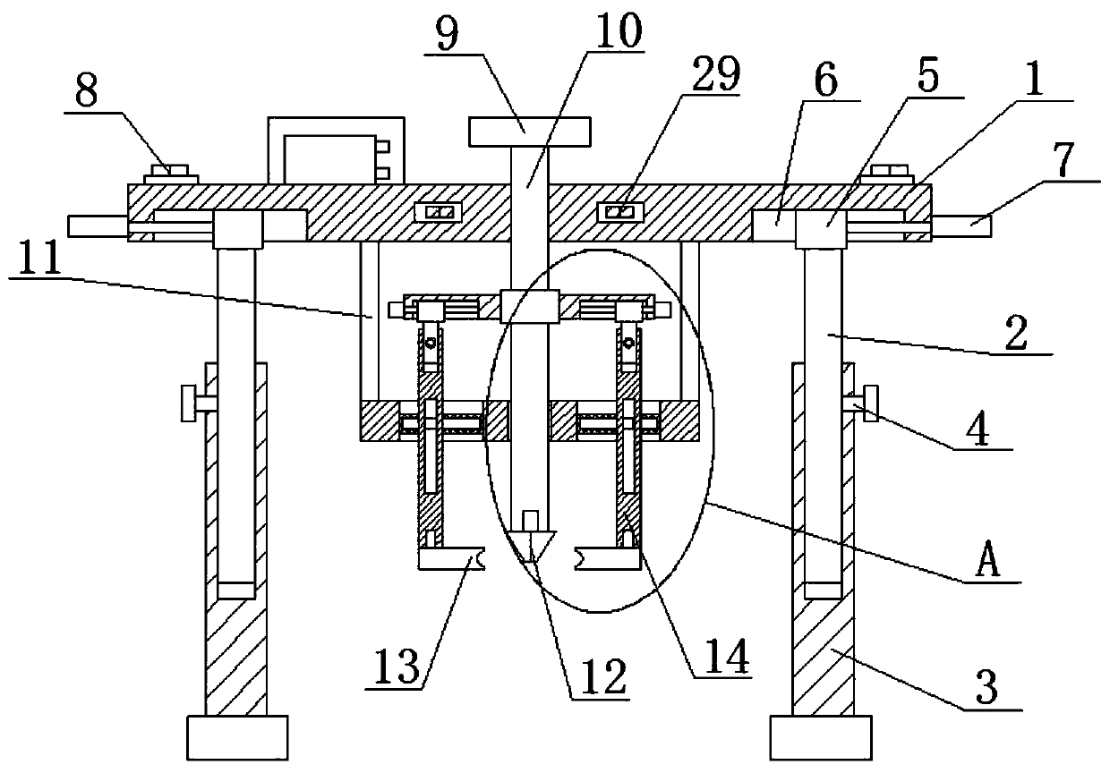
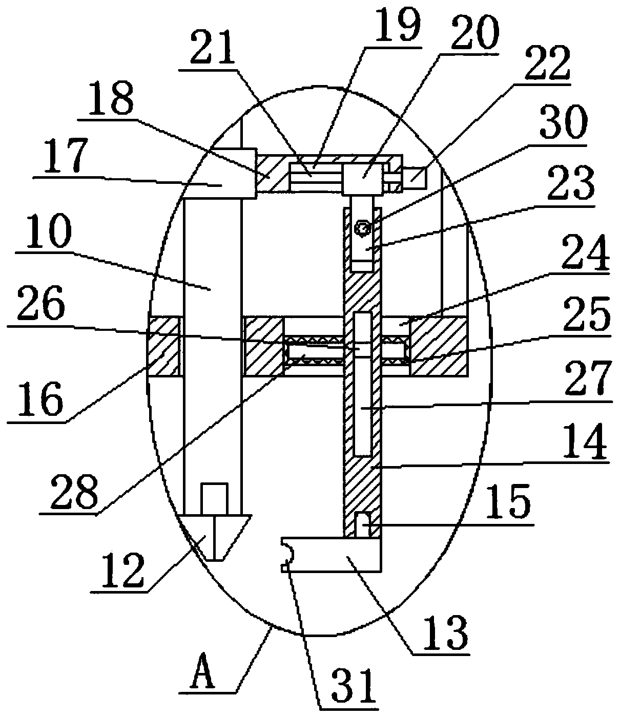
[0030] refer to Figure 1-5 , a nail removal device used in orthopedics, comprising a horizontal plate 1, a threaded rod 10 is threaded at the center of the horizontal plate 1, a screw head 12 is connected to the bottom end of the threaded rod 10, and the bottom of the horizontal plate 1 is symmetrically slidably installed There are two telescopic legs 2, the outer sides of the two telescopic legs 2 are slidingly installed with support legs 3, the bottom of the horizontal plate 1 is fixedly installed with two welding rods 11, and the bottom of the two welding rods 11 is fixedly installed with the same welding plate 16, the threaded rod 10 is threadedly connected with the welded plate 16, and two adjustment holes 24 are symmetrically opened on the welded plate 16, and two transverse support rods 25 are horizontally fixedly installed in the two adjustment holes 24, and two horizontal support rods 25 are fixed in the two adjustment holes 24. Both are movably connected with a clam...

Embodiment 2

[0040] refer to Figure 1-5 , a nail removal device used in orthopedics, comprising a horizontal plate 1, a threaded rod 10 is threaded at the center of the horizontal plate 1, a screw head 12 is connected to the bottom end of the threaded rod 10, and the bottom of the horizontal plate 1 is symmetrically slidably installed There are two telescopic legs 2, the outer sides of the two telescopic legs 2 are slidingly installed with supporting legs 3, the bottom of the horizontal plate 1 is fixedly installed with two welding rods 11 by welding, and the bottoms of the two welding rods 11 are fixed and installed by welding There is the same welding plate 16, the threaded rod 10 is threadedly connected with the welding plate 16, and the welding plate 16 is symmetrically provided with two adjustment holes 24, and two transverse support rods 25 are fixedly installed in the two adjustment holes 24 by welding in the horizontal direction. Clamping rods 14 are movably connected in the two a...


PUM


Abstract

The invention belongs to the technical field of medical equipment, and concretely relates to a nail taking device for orthopedics, existing screw taking modes are mostly used through screwdrivers, thescrews often fall off, during twisting, the screw is stressed unevenly and is capable of easily slipping, proposed now is the following scheme, the device comprises a transverse plate, a threaded rodis in threaded connection with the central position of the transverse plate; the bottom end of the threaded rod is connected with a screw head; two telescopic legs are symmetrically mounted at the bottom of the transverse plate in a sliding manner; supporting legs are slidably mounted on the outer sides of the two telescopic legs correspondingly, two welding rods are fixedly mounted at the bottomof the transverse plate, the same welding plate is fixedly mounted at the bottoms of the two welding rods correspondingly, the threaded rod is in threaded connection with the welding plate, two adjusting holes are symmetrically formed in the welding plate, and two transverse supporting rods are transversely and fixedly mounted in the two adjusting holes correspondingly. According to the screw taking device, screws can be clamped during screw taking, the screws are prevented from falling off, and the screw taking device can adapt to screws of different sizes.

Description

technical field [0001] The invention relates to the technical field of medical equipment, in particular to a nail removing device used in orthopedics. Background technique [0002] In orthopedic treatment, the fracture site is usually connected with a steel plate, and the steel plate connection needs to be fixed with screws. When performing bone fixation recovery treatment for patients with fractures and bone fractures, the steel plate needs to be removed. It is necessary to remove the steel plate and remove the nails. of. [0003] The existing nail removal methods are mostly used by a screwdriver, which often causes the screw to fall off, and the screw is unevenly stressed when twisted, and it is easy to slip off. Contents of the invention [0004] The purpose of the present invention is to solve the shortcomings that the existing screwdriver is often used for removing screws, and the screws often fall off, and the screws are unevenly stressed during twisting, and are ea...

Claims


Application Information

Patent Timeline
Patent Type & Authority Applications(China)
IPC IPC(8): A61B17/92
CPCA61B17/92A61B2017/564
Inventor 王衍武
Owner 王衍武
Why Eureka
Try Eureka