Rotary steering tool for well drilling

A rotary steering and tool technology, applied in drilling equipment, directional drilling, drilling automatic control system, etc., can solve the problems of drill string torque, large friction, incomplete wellbore cleaning, slow ROP, etc., and achieve high performance Reliable, simple and inexpensive effect

Pending Publication Date: 2020-06-16
四川海斯特能源技术有限责任公司
View PDF0 Cites 6 Cited by
  • Summary
  • Abstract
  • Description
  • Claims
  • Application Information

AI Technical Summary

Problems solved by technology

Sliding steering has many disadvantages: the torque and friction of the drill string are large; the wellbore cleaning is not thorough; the ROP is slow, etc., but it still dominates
[0010] At present, the rotary steerable tools used in my country's shale gas market are basically monopolized by a few foreign companies such as Schlumberger, Baker Hughes, and Halliburton. The tools have excellent performance and a high degree of automation, but the structure is very complicated and the price is very high. expensive

Method used


Image

  • Rotary steering tool for well drilling
  • Rotary steering tool for well drilling
  • Rotary steering tool for well drilling

Examples


Embodiment Construction

[0030] The present invention will be described in detail below in conjunction with the accompanying drawings.

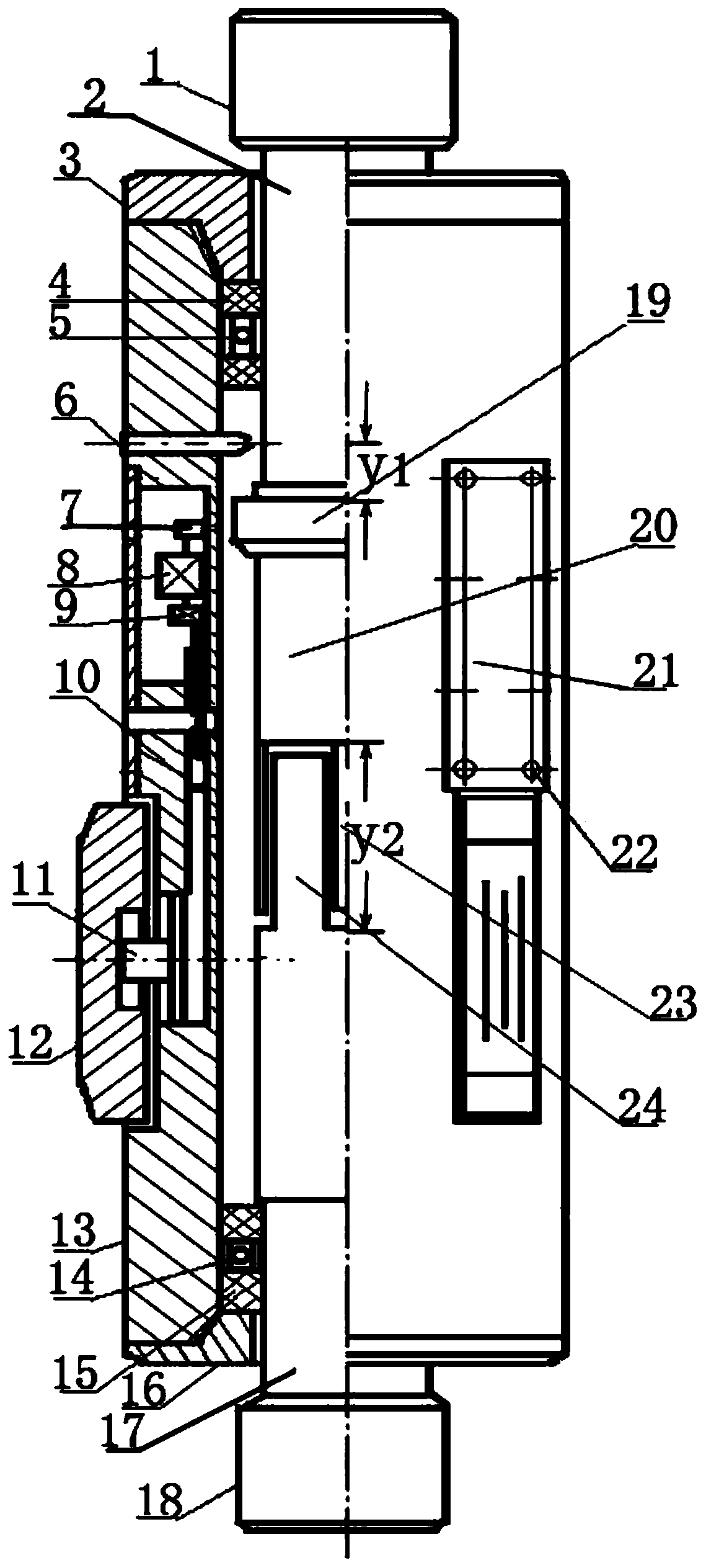
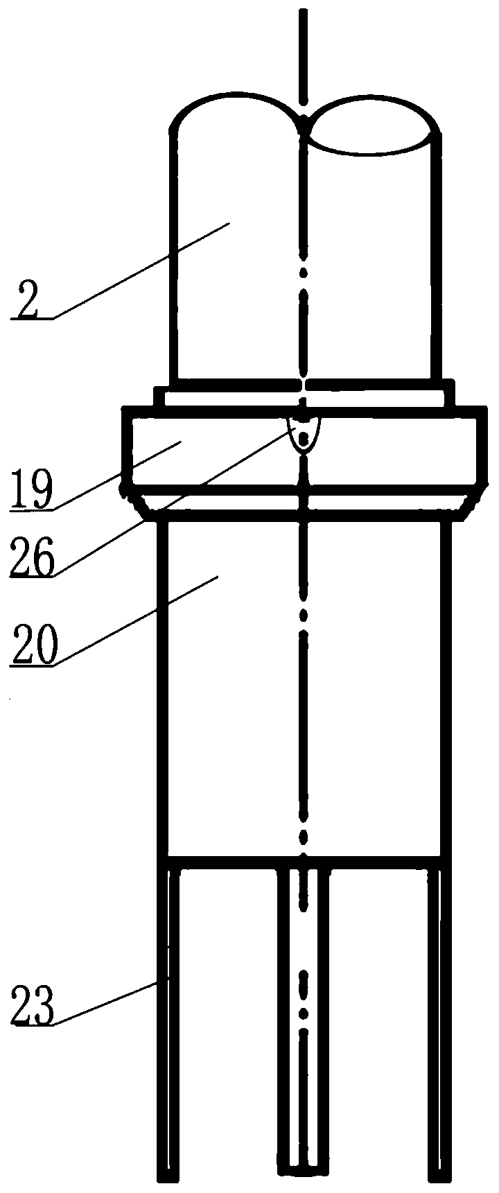
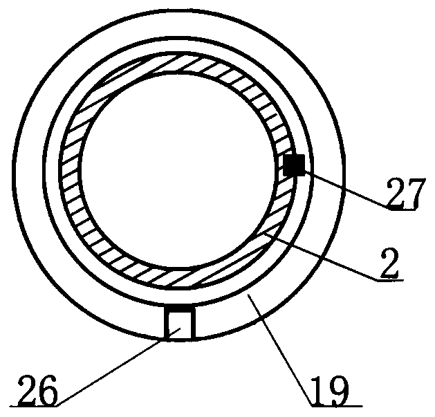
[0031] see figure 1 , figure 2 , image 3 , Figure 4 .

[0032] The tool includes an upper hollow joint 1, a threaded head with an integral structure and a light pipe section 2, the threaded head faces upwards, and is used to connect a drill string; a coupling sleeve 20 is sleeved on the periphery of the light pipe section 2, and the coupling sleeve 20 and the light pipe section 2 are passed through Ying fit, the mating surface is provided with an axial key 27, and the lower end of the light pipe section 2 is an inlay 23.

[0033] The lower hollow joint 18 has a threaded head and a bare pipe section 17 of an integral structure, and the threaded head faces downward for connecting a drill bit. The upper end of the light pipe section 17 is a tooth insert 24, which is engaged with the lower end tooth insert 23 of the light pipe section 2 to transmit torque .

[0...


PUM


Abstract

The invention discloses a rotary steering tool for well drilling. The rotary steering tool for well drilling comprises a pair of hollow joints arranged up and down and in butt joint, wherein each hollow joint is provided with a threaded head section and a light pipe section which are of an integral structure, the threaded head sections of the upper hollow joint and the lower hollow joint are oppositely arranged, the light pipe sections of the upper hollow joint and the lower hollow joint are each provided with a rolling bearing, an outer sleeve is arranged on the periphery of each rolling bearing, and the outer sleeves are supported on the rolling bearings; three hollow windows arranged in the circumferential direction are formed in each outer sleeve, wherein each hollow window is providedwith a supporting block, each supporting block is provided with a hydraulic cylinder, and the hydraulic cylinders drive the supporting blocks to stretch out along the hollow windows and abut againstthe well wall with mud pressure difference between the interior and the exterior of a drill column as power; when no pressure difference exists between the inner mud and the outer mud of the drill column, reset springs of the hydraulic cylinders enable the supporting block to retract; and a mud channel is formed in the connecting portion of the upper hollow joint and the lower hollow joint, so that mud in the tool enters the hydraulic cylinder, and pistons can be driven to push the supporting blocks to stretch out; one hydraulic cylinder of one supporting block is further provided with a reversing valve which is used for enabling the hydraulic cylinder of the supporting block to communicate with the mud in the drill column or the mud outside the drill column. According to the rotary steering tool for well drilling, a stable inclined drilling working mode, a rotary steering working mode, a full-closed tripping working mode and a tripping working mode can be selectively realized.

Description

technical field [0001] The invention belongs to the field of oil drilling and production tools, and relates to a rotary steering tool for drilling. Background technique [0002] The rotary steerable drilling system is an advanced trajectory control system for directional wells and horizontal wells developed abroad in the last century. ) an indispensable base platform. Since the beginning of this century, various domestic oil fields and institutes have carried out a lot of research and development on rotary steerable systems, and achieved a series of results. Expensive, and no official product has been put into commercial application. [0003] Steering drilling is realized mainly by steering tools, which are divided into two categories: [0004] 1. Sliding guide tool [0005] The characteristic of the sliding steering tool is that the drill string does not rotate during the steering operation, and the drill string is pushed forward with the drill bit and slides along the ...

Claims


Application Information

Patent Timeline
Patent Type & Authority Applications(China)
IPC IPC(8): E21B7/04E21B7/06E21B7/08E21B44/00
CPCE21B7/04E21B7/06E21B44/00
Inventor 周跃云范翔宇谢炜汪丹强瑜陈林
Owner 四川海斯特能源技术有限责任公司
Why Eureka
Try Eureka