Blade rotating compressor

A compressor and casing technology, applied in the field of compressors, can solve problems such as small compression volume, leakage between sliding vane and cylinder wall, large friction and wear, and pulsation of air flow, so as to increase energy conversion efficiency and increase energy conversion Good results in efficiency, sealing and durability

Active Publication Date: 2020-06-16
李炳强
View PDF5 Cites 0 Cited by
  • Summary
  • Abstract
  • Description
  • Claims
  • Application Information

AI Technical Summary

Problems solved by technology

[0003] Disadvantages of piston compressors: complex and heavy structure, vibration during machine operation, discontinuous exhaust, and pulsation of air flow; disadvantages of rolling rotor compressors: large leakage, friction and wear between the sliding vane and the cylinder wall, compression The volume is small; the manufacturing cost of the scroll compressor is high, eccentric vibration, and the surface of its moving parts is mostly in the shape of a curved surface. The processing and inspection of these curved surfaces are more complicated, and the manufacturing requires high-precision processing equipment and precise adjustment. Center assembly technology, so the manufacturing cost is high, between the moving parts or between the moving parts and the fixed parts, often maintain a certain movement gap to achieve sealing, the gas passing through the gap will inevitably cause leakage, which limits the rotary type It is difficult for compressors to achieve a large compression ratio. Therefore, most rotary compressors are mostly used in air-conditioning conditions; screw compressors have high compressor noise and cannot be used in high-pressure situations. Screw compressors rely on gaps to seal gas. Does not have superior performance in the small volume range

Method used


Image

  • Blade rotating compressor
  • Blade rotating compressor
  • Blade rotating compressor

Examples


Embodiment Construction

[0061] Various components of a rotary engine.

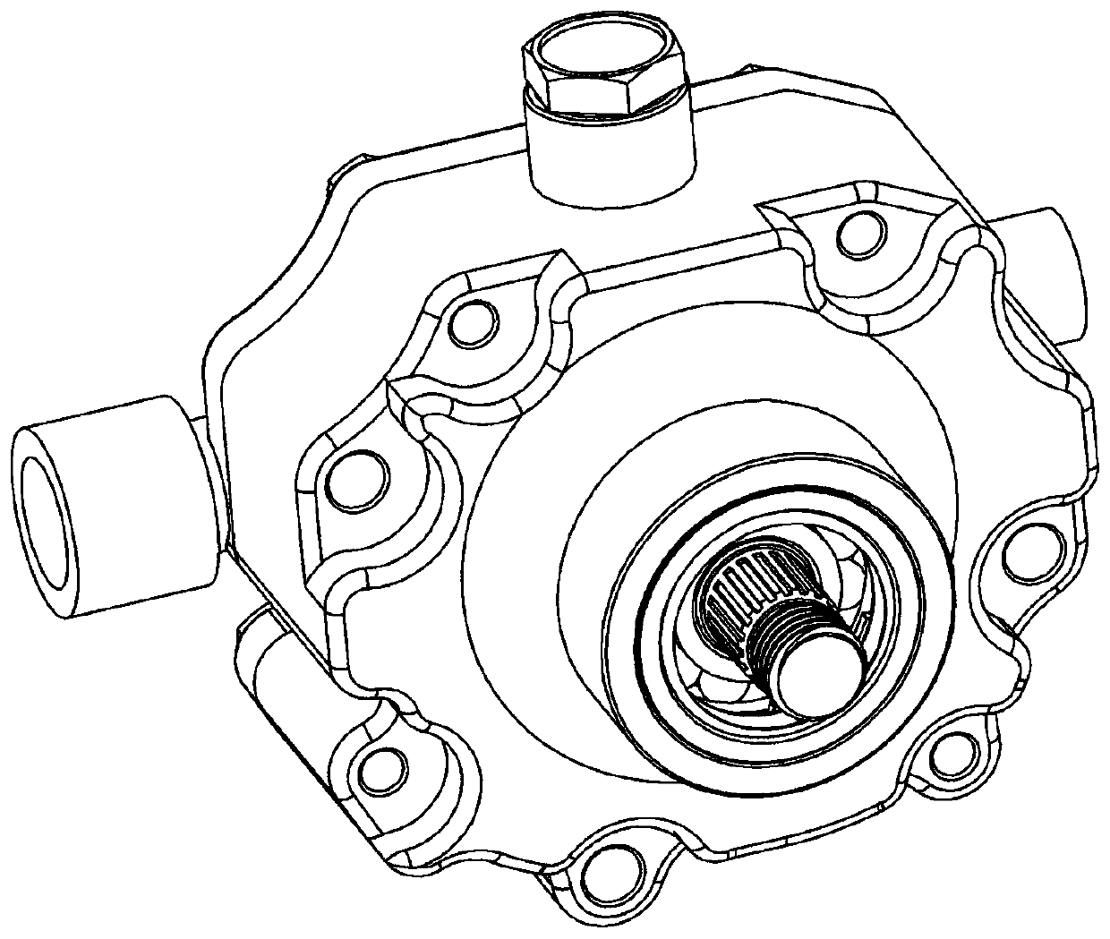
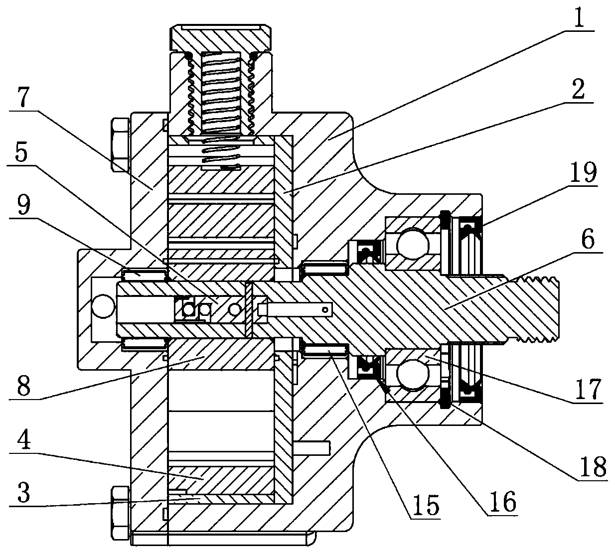
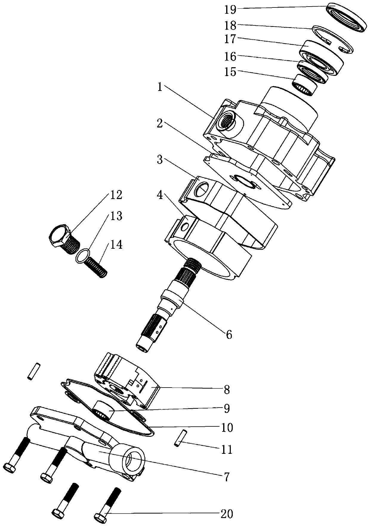
[0062] Such as figure 1 , 2 , 3, 4, 5, 14, 21, 25, this compression is made up of rotor assembly (8), casing assembly (59) (7), drive shaft assembly (60) three parts. and construct as Figure 31 The compression train (A) of the compressor shown, Figure 32 lubricating cooling system (B), Figure 4 The constant pressure system (C), figure 1 The external view of the compressor, figure 2 sectional view of the compressor, image 3 Compressor structure assembly diagram, Figure 4 It is a perspective view of the compressor structure.

[0063] Such as Figures 5 to 13 As shown, the components of the rotor assembly (8) include leaf A (22), leaf B (23), rotor seat (21), and the leaf (22) (23) and rotor seat (21) are connected through the leaf shaft (27) Hinged connection, the hinged seal is composed of the leaf shaft seal (28), and the two ends of the return spring (30) in the leaf shaft seal (28) are fixed in the corresponding...


PUM


Abstract

A blade rotating compressor is composed of a rotor, a shell and a transmission shaft. A cavity formed between the rotor and the shell is divided into air cylinders and lubricating cylinders, four blades are mounted on the rotor to rotate in the shell in a step-by-step hinge mode and revolve along with the rotor, two adjacent bosses of the rotor are divided by two adjacent blades and the shell intocylinders, namely compression cylinders, and the same boss is divided by two adjacent blades and the shell into lubricating cylinders. In the operation process, the volumes of the air cylinders and the lubricating cylinders formed by the two adjacent blades and the shell are variable, and the volumes of other air cylinders and lubricating cylinders are correspondingly variable at the same time. The volumes are changed so as to achieve the air suction, compression and exhaust process, the two opposite air cylinders and the lubricating cylinders are opposite in stroke, and the strokes are simultaneously carried out. The air cylinders do work for compression, the lubricating cylinders lubricate and cool components, and the transmission shaft directly drives the rotor to rotationally do work.

Description

technical field [0001] The invention relates to a novel compressor, a pump and pneumatic equipment, in particular to a compressor with a large power-to-weight ratio, no vibration, and applied to large, medium and small equipment. Background technique [0002] At present, among the existing compressors, there are mainly reciprocating piston compressors, rotary compressors, scroll compressors, and screw compressors. [0003] Disadvantages of piston compressors: complex and heavy structure, vibration during machine operation, discontinuous exhaust, and pulsation of air flow; disadvantages of rolling rotor compressors: large leakage, friction and wear between the sliding vane and the cylinder wall, compression The volume is small; the manufacturing cost of the scroll compressor is high, eccentric vibration, and the surface of its moving parts is mostly in the shape of a curved surface. The processing and inspection of these curved surfaces are more complicated, and the manufactu...

Claims


Application Information

Patent Timeline
IPC IPC(8): F04C18/44F04C23/00F04C27/00F04C29/00F04C29/02F04C29/04
CPCF04C18/44F04C23/001F04C27/005F04C29/00F04C29/02F04C29/025F04C29/04F04C2240/20F04C2240/30F04C2240/60
Inventor 不公告发明人
Owner 李炳强
Why Eureka
Try Eureka