Gas-liquid separating and liquid recycling device

A technology of liquid circulation and gas-liquid separation, applied in separation methods, components of pumping devices for elastic fluids, separation of dispersed particles, etc., can solve the problems that cannot meet the needs of liquid ring pumps, technical problems, and reduction of working fluid To achieve the effect of protecting gas tightness, improving retention capacity, and expanding adsorption capacity

Inactive Publication Date: 2020-06-16
罗辉
View PDF1 Cites 0 Cited by
  • Summary
  • Abstract
  • Description
  • Claims
  • Application Information

AI Technical Summary

Problems solved by technology

[0004] The gas-liquid cooling separation device used in the liquid ring pump will generate a momentary increase in pressure due to the change in the speed of the liquid ring pump during the instant start-up and low-gear switching to high-low process. This pressure will make the working fluid inside the square tank The surface is pressed down instantly, causing the working fluid inside the square tank to overflow from the overflow pipe, resulting in a large reduction of working fluid, which cannot meet the use of liquid ring pumps, especially when the working fluid level is low, and even causes gas leakage
[0005] For example, the patent document CN201610752389.4 discloses a gas-liquid cooling and separation device and a refrigeration or heat pump device with the gas-liquid separator. The gas-liquid separator includes a cylinder, a refrigerant inlet pipe, a gaseous refrigerant outlet pipe, Liquid refrigerant outlet pipe and flow regulating device, the flow regulating device is used to adjust the refrigerant flow rate of gaseous refrigerant outlet pipe or liquid refrigerant outlet pipe, but this patent cannot solve the above technical problems

Method used


Image

  • Gas-liquid separating and liquid recycling device
  • Gas-liquid separating and liquid recycling device
  • Gas-liquid separating and liquid recycling device

Examples


Embodiment 1

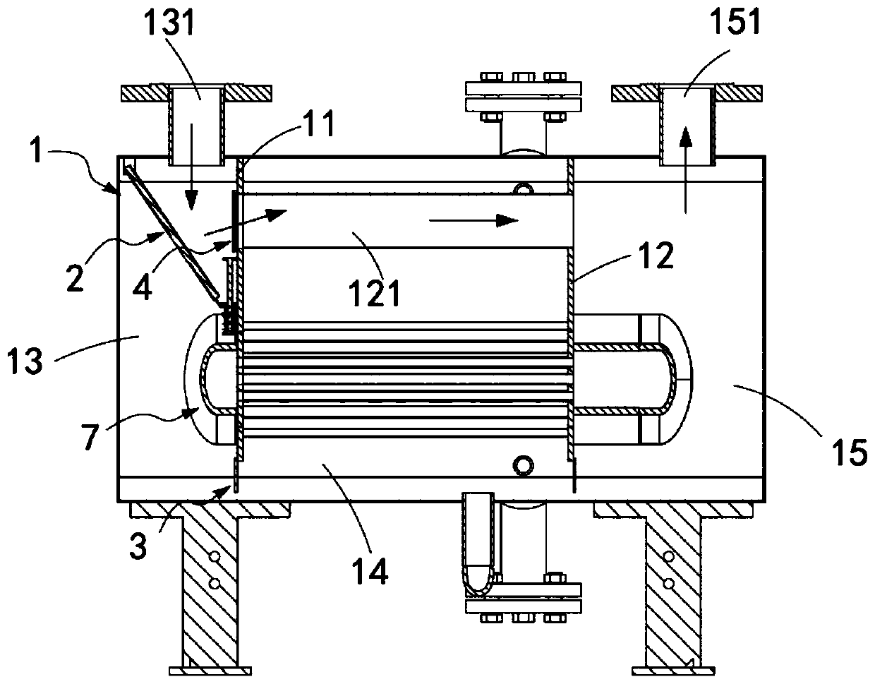
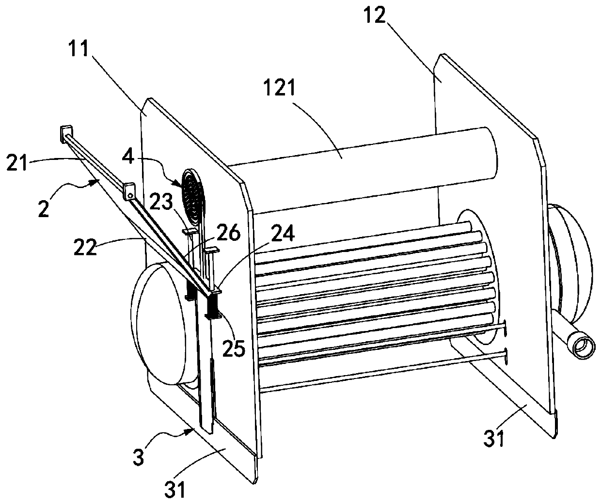
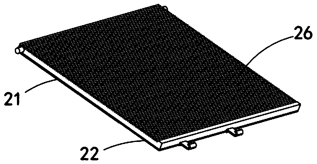
[0057] Such as Figure 1 to Figure 4 As shown, a gas-liquid separation liquid recycling device includes a square tank body 1, a first partition 11 and a second partition 12 are arranged in the square tank body 1, so that the square tank body 1 is sequentially arranged along the length direction Divided into a first compartment 13, a second compartment 14 and a third compartment 15, and the first compartment 13, the second compartment 14 and the third compartment 15 pass through the first partition 11 and the third compartment 15. The communication port 111 provided at the bottom of the second partition 12 communicates, and an exhaust pipe communicating with the first compartment 13 and the third compartment 15 is provided between the first partition 11 and the second partition 12 112, the top of the first compartment 13 is provided with a waste gas liquid inlet 131, the top of the third compartment 15 is provided with a waste gas discharge port 151 for discharging waste gas, a...


PUM


Abstract

The invention relates to the technical field of gas-liquid separation, in particular to a gas-liquid separating and liquid recycling device. According to the gas-liquid separating and liquid recyclingdevice, a guiding plate mechanism is used for being matched with air pressure at an exhaust gas liquid inlet, when the air pressure at the exhaust gas liquid inlet is increased, the liquid content isincreased, the increased air pressure enables the guiding plate mechanism to swing, an upper guiding plate and a lower guiding plate slide mutually, the contact area between a sponge plate on the guiding plate mechanism and the exhaust gas liquid inlet is enlarged, the adsorption capacity of a liquid is enlarged, and the technical problem that due to the fact that when a pump body is started to work, the air pressure at the exhaust gas liquid inlet is instantaneously increased, the amount of the liquid is increased is solved; and meanwhile, swinging of the guiding plate mechanism is used fordriving a gate plate mechanism and a liquid retention mechanism to work, and the liquid retention mechanism further adsorbs the liquid, so that the retention capacity of the liquid is improved, and the gate plate mechanism can reduce the height of a communicating opening, so that the situation that the pressure lowers the liquid surface, so that gas is leaked is avoided.

Description

technical field [0001] The invention relates to the technical field of gas-liquid separation equipment, in particular to a gas-liquid separation liquid recycling device. Background technique [0002] Liquid ring pumps were originally used as self-priming pumps, and then gradually used in many industrial sectors such as petroleum, chemical industry, machinery, mining, light industry, medicine and food. In many processes of industrial production, such as vacuum filtration, vacuum water diversion, vacuum Water ring pumps are widely used in feeding, vacuum evaporation, vacuum concentration, vacuum moisture regain and vacuum degassing, etc. Due to the rapid development of vacuum application technology, water ring pumps have been paid attention to in obtaining rough vacuum. Since the gas compression in the water ring pump is isothermal, it can pump out flammable and explosive gases, in addition to dusty and water-containing gases. [0003] Therefore, there is a need for a gas-li...

Claims


Application Information

Patent Timeline
Patent Type & Authority Applications(China)
IPC IPC(8): F04C29/00F04C29/04B01D45/08B01D53/26
CPCB01D45/08B01D53/26F04C29/0092F04C29/04
Inventor 罗辉
Owner 罗辉
Why Eureka
Try Eureka