Vibration table test loading device with load decoupling function and using method

A technology of shaking table test and loading device, which is applied in vibration test, foundation structure test, measuring device, etc. It can solve problems such as inability to decouple, slow progress in research on physical model tests of seismic load effects on pile foundations, etc., and improve execution efficiency Effect

Active Publication Date: 2020-06-16
HARBIN INST OF TECH
View PDF6 Cites 0 Cited by
  • Summary
  • Abstract
  • Description
  • Claims
  • Application Information

AI Technical Summary

Problems solved by technology

Because this loading technique naturally has the disadvantage of being unable to decouple the axial load and inertial load from the superstructure, the research on the physical model test of the seismic load effect on pile foundations has been slow.

Method used


Image

  • Vibration table test loading device with load decoupling function and using method
  • Vibration table test loading device with load decoupling function and using method
  • Vibration table test loading device with load decoupling function and using method

Examples


specific Embodiment approach 1

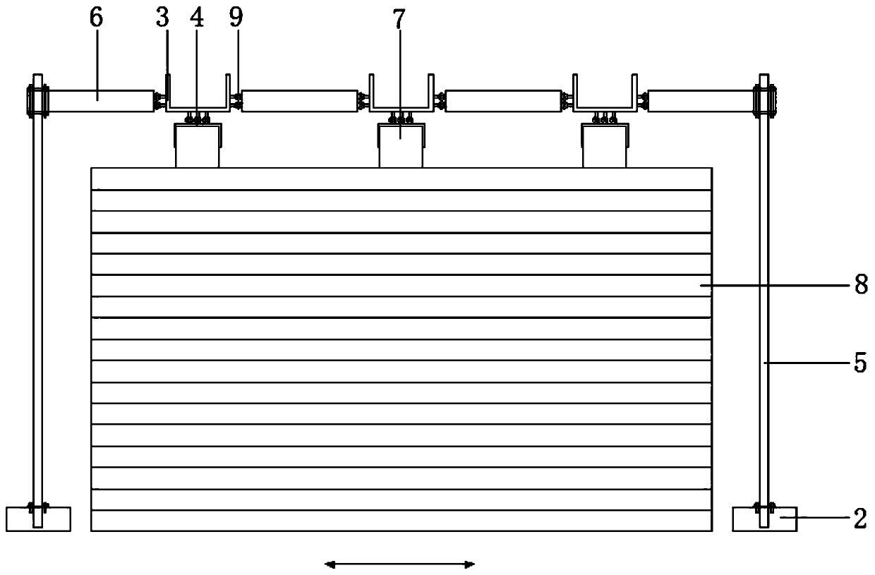
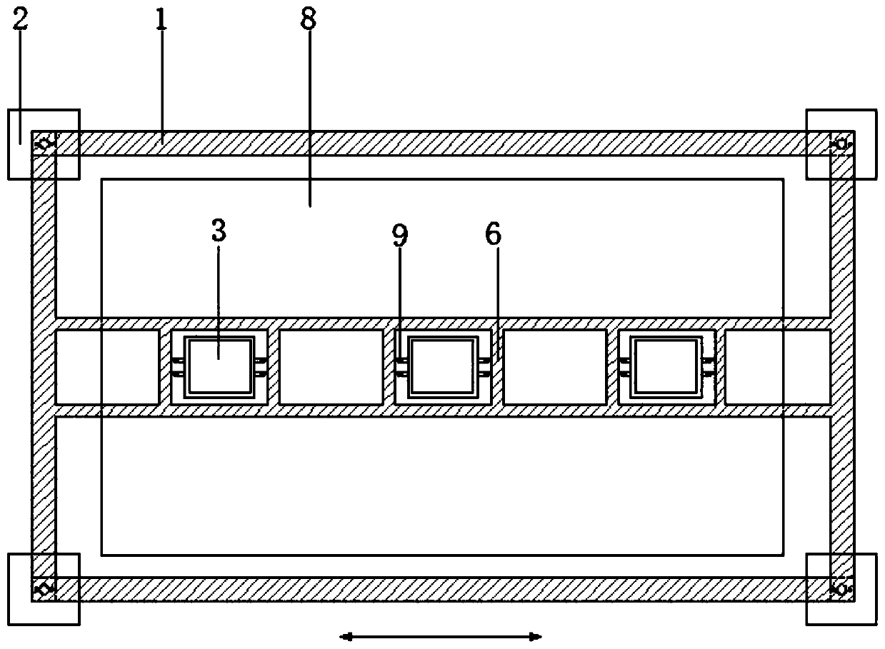
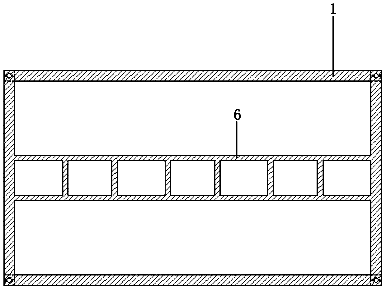
[0024] Specific implementation mode one: as Figure 1 ~ Figure 3 As shown, the present invention discloses a shaking table test loading device with a load decoupling function, which includes a lateral limit frame 1, a lateral limit frame 6, four counterweight column feet 2, four hollow steel pipes 5, and a plurality of guide cars 3 and a plurality of pile head baffles 4; the four counterweight column feet 2 are arranged on the outside of the vibration table 8 along the circumference of the vibration table 8, and the lateral limit frame 1 is horizontally arranged on the upper ends of a plurality of model piles 7 And through four hollow steel pipes 5 and four counterweight column feet 2 one-to-one detachable fixed connection (side limit frame 1 is a rectangular frame, the four corners of the rectangular frame and the middle part of each counterweight column foot 2 are set There are mounting holes, the lower end of each corner of the rectangular frame and the upper end of each co...

specific Embodiment approach 2

[0025] Specific embodiment 2: This embodiment is a further description of specific embodiment 1. The lateral limit frame 1, the lateral limit frame 6, the four counterweight column feet 2, the four hollow steel pipes 5, and a plurality of guide cars 3 And a plurality of pile head baffles 4 are all prefabricated by steel.

specific Embodiment approach 3

[0026] Specific implementation mode three: as figure 1 As shown, this embodiment is a further description of the second embodiment, and the four counterweight column feet 2 are arranged in a rectangular array.


PUM


Abstract

The invention discloses a vibration table test loading device with a load decoupling function and a using method, which belong to the technical field of vibration table tests. The vibration table testloading device comprises balance weight column feet which are arranged on the outer side of a vibration table and connected with a side limiting rack through using hollow steel pipes, wherein a pilehead baffle sleeves a pile head of a model pile, a side limiting frame is arranged in the side limiting rack, a guide vehicle is arranged in the side limiting frame, and the guide vehicle is placed onthe pile head baffle and provided with a pulley attached to the side limiting frame and the pile head baffle. The using method comprises the steps of: designing and prefabricating the size of each part, sleeving the pile head baffle on the pile head of the model pile, smearing lubricating oil on the pile head baffle and the side limiting frame, determining the positions of the counterweight column feet, assembling all the parts one by one, placing the guide vehicle in the side limiting frame, and placing a mass block in the guide vehicle. According to the vibration table test loading device with the load decoupling function and the using method, the influence of inertia load from an upper structure is eliminated while the model pile is axially loaded, the execution efficiency of the testis greatly improved, and the vibration table test loading device is quick to install, easy to disassemble, energy-saving and environment-friendly.

Description

technical field [0001] The invention relates to a vibration table test loading device with a load decoupling function and a use method thereof, belonging to the technical field of vibration table tests. Background technique [0002] Since 2000, my country's mainland has entered a new period of seismic activity, with an average of 20 earthquakes of magnitude 5 or above, 3.8 earthquakes of magnitude 6 or above, and 0.6 earthquakes of magnitude 7 or above, and the damage to pile foundation structures is serious. Therefore, the seismic response analysis of pile foundation engineering has become an important and concerned scientific issue. [0003] Loading of pile foundations under earthquake is an extremely complex problem, which often involves a series of simultaneous and mutually compensating loads, including axial loads from the superstructure, inertial loads, and pile-soil dynamic interactions. [0004] In order to ascertain the load mechanism and failure mechanism of pile ...

Claims


Application Information

Patent Timeline
Patent Type & Authority Applications(China)
IPC IPC(8): G01M7/02E02D33/00
CPCE02D33/00G01M7/02
Inventor 唐亮李雪伟张效禹孟畅满孝峰凌贤长
Owner HARBIN INST OF TECH
Why Eureka
Try Eureka