Test device and method for observing behavior of flowing boiling bubbles in micro-channel

A test device and microchannel technology, applied in the field of physical measurement, can solve the problems of lack of bubble dynamics, achieve the effect of convenient flow of working fluid, reduce test time, and facilitate research

Inactive Publication Date: 2020-06-16
QINGDAO TECHNOLOGICAL UNIVERSITY
View PDF0 Cites 3 Cited by
  • Summary
  • Abstract
  • Description
  • Claims
  • Application Information

AI Technical Summary

Problems solved by technology

[0006] Aiming at the deficiencies in the prior art, the purpose of the present invention is to provide a test device and method for observing the behavior of flow boiling bubbles in a microc

Method used


Image

  • Test device and method for observing behavior of flowing boiling bubbles in micro-channel
  • Test device and method for observing behavior of flowing boiling bubbles in micro-channel

Examples


Embodiment 1

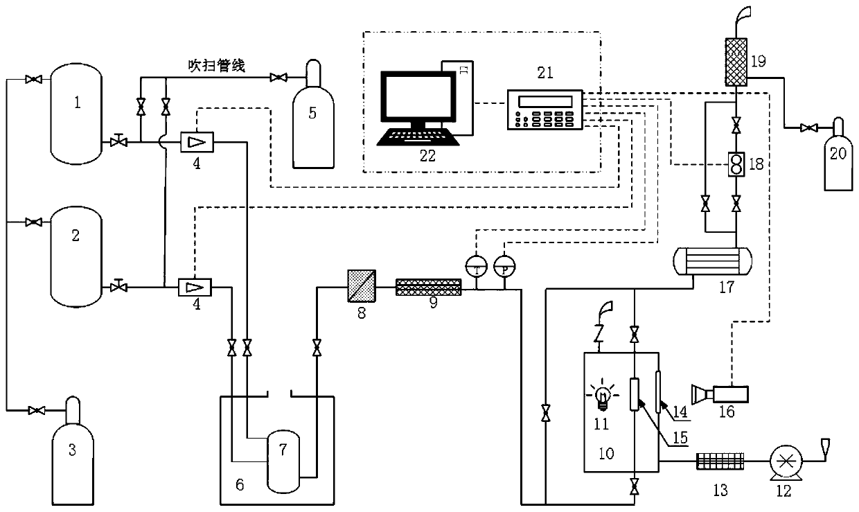
[0039] In a typical embodiment of the present invention, as figure 1 As shown, a test device for observing the behavior of flowing and boiling bubbles in a microchannel includes a liquid dispensing mechanism, a purging mechanism, an observation mechanism, a venting mechanism, a data monitoring and collection mechanism, and pipes, pipe fittings, valves, etc. connecting various equipment. The liquid mechanism is connected to the observation mechanism, and the liquid dispensing mechanism can provide the observation mechanism with a mixed working fluid composed of precise components; the purging mechanism is connected to all the pipelines in this embodiment, and all pipelines here include connections for various The pipeline between the mechanism and the microchannel, as well as the pipeline of the microchannel itself, the purging mechanism blows nitrogen into the test mechanism and the pipeline before and after the test, and the observation mechanism is used for the observation of...

Embodiment 2

[0066] This embodiment discloses a test method for observing the behavior of flowing and boiling bubbles in a microchannel. It should be stated first that all valves in the test device are closed before a set of tests starts; the following steps are included:

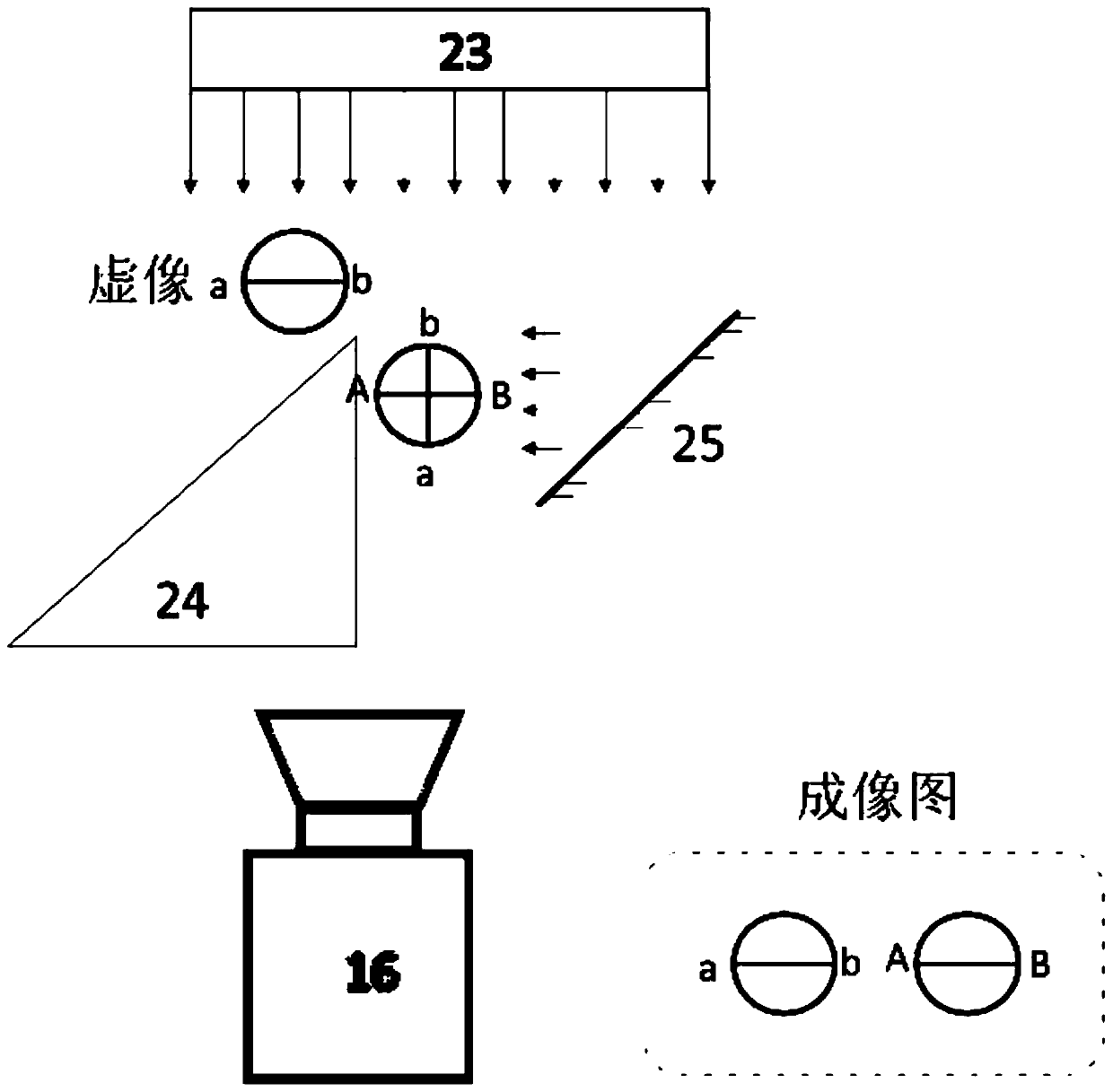
[0067] Step 1: Preset the data of the mass flow meter as two groups A and B; install the micro-channel, and debug the LED light source 11 and the camera 16;

[0068] Step 2: Open the valve of the safety venting device 19, the front and rear valves of the volumetric flowmeter 18, the front and rear valves of the microchannel, and the inlet valve of the mixing tank 7 to purge the nitrogen branch pipe valve; keep the volumetric flowmeter 18 bypass valve, microchannel bypass valve, The dosing system valve is closed;

[0069] Step 3: Open the purging nitrogen cylinder 5 valve to purge the pipeline;

[0070] Step 4: close the valve of the purge nitrogen cylinder 5 and the purge nitrogen branch pipe valve;

[0071] Step 5: o...


PUM


Abstract

The invention discloses a test device and method for observing the behavior of flowing boiling bubbles in a micro-channel, which belongs to the field of physical measurement. The device comprises a camera, a mass flow meter and a liquid preparation device, wherein the camera is arranged outside a drying box and can observe the interior of the drying box, and a light source is also arranged in thedrying box; the micro-channel is arranged in the drying box; the liquid preparation device is communicated with the micro-channel, the mass flow meter is connected to the liquid preparation device, and the mass flow meter is connected to the server; the liquid preparation device comprises a mixing tank and a plurality of liquid storage tanks, the plurality of liquid storage tanks are communicatedwith the mixing tank, and the mixing tank is communicated with one end of the channel; and the other end of the micro-channel is also communicated with an emptying mechanism. The device can solve theproblem that a test device for researching flowing boiling heat exchange and bubble dynamic characteristics of a non-azeotropic mixed working medium in a micro-channel does not exist at present.

Description

technical field [0001] The invention belongs to the field of physical measurement, and in particular relates to a test device and method for observing the behavior of flowing and boiling bubbles in a microchannel. Background technique [0002] The statements herein merely provide background related to the present invention and do not necessarily constitute prior art. [0003] Microchannel heat exchangers refer to heat exchangers with a channel equivalent diameter of 10 to 2000 μm. As an emerging heat exchange technology, microchannel heat exchangers are widely used in the fields of chip heat dissipation, aerospace, HVAC, fuel cells, natural gas liquefaction, etc. application prospects. [0004] Compared with traditional heat exchangers, micro-channel heat exchangers have a small channel size, weaker gravitational effects on the working medium, and prominent surface tension effects, and the bubble behavior in flow boiling exhibits obvious micro-scale effects. The character...

Claims


Application Information

Patent Timeline
IPC IPC(8): G01N21/85G01N21/01G01M10/00
CPCG01M10/00G01N21/01G01N21/85
Inventor 刘纳孟祥丰
Owner QINGDAO TECHNOLOGICAL UNIVERSITY
Why Eureka
Try Eureka