Optical current transformer error compensation method based on DE-SVM

A technology of DE-SVM and current transformer, which is applied in the direction of instruments, measuring electrical variables, measuring devices, etc., can solve the problems of high cost and falling into local optimum

Inactive Publication Date: 2020-06-16
GUANGDONG POWER GRID CO LTD +1
View PDF3 Cites 0 Cited by
  • Summary
  • Abstract
  • Description
  • Claims
  • Application Information

AI Technical Summary

Problems solved by technology

[0008] In order to overcome the shortcomings of the existing optical current transformer error compensation using complex mathematical models or algorithms that are easy to fall into local optimum, and the direct transformation of the optical current transformer body equipment has the disadvantage of high cost, the present invention proposes a DE-based -SVM's optical current transformer error compensation method avoids the high cost of falling into local optimum and transforming equipment

Method used


Image

  • Optical current transformer error compensation method based on DE-SVM
  • Optical current transformer error compensation method based on DE-SVM
  • Optical current transformer error compensation method based on DE-SVM

Examples


Embodiment 1

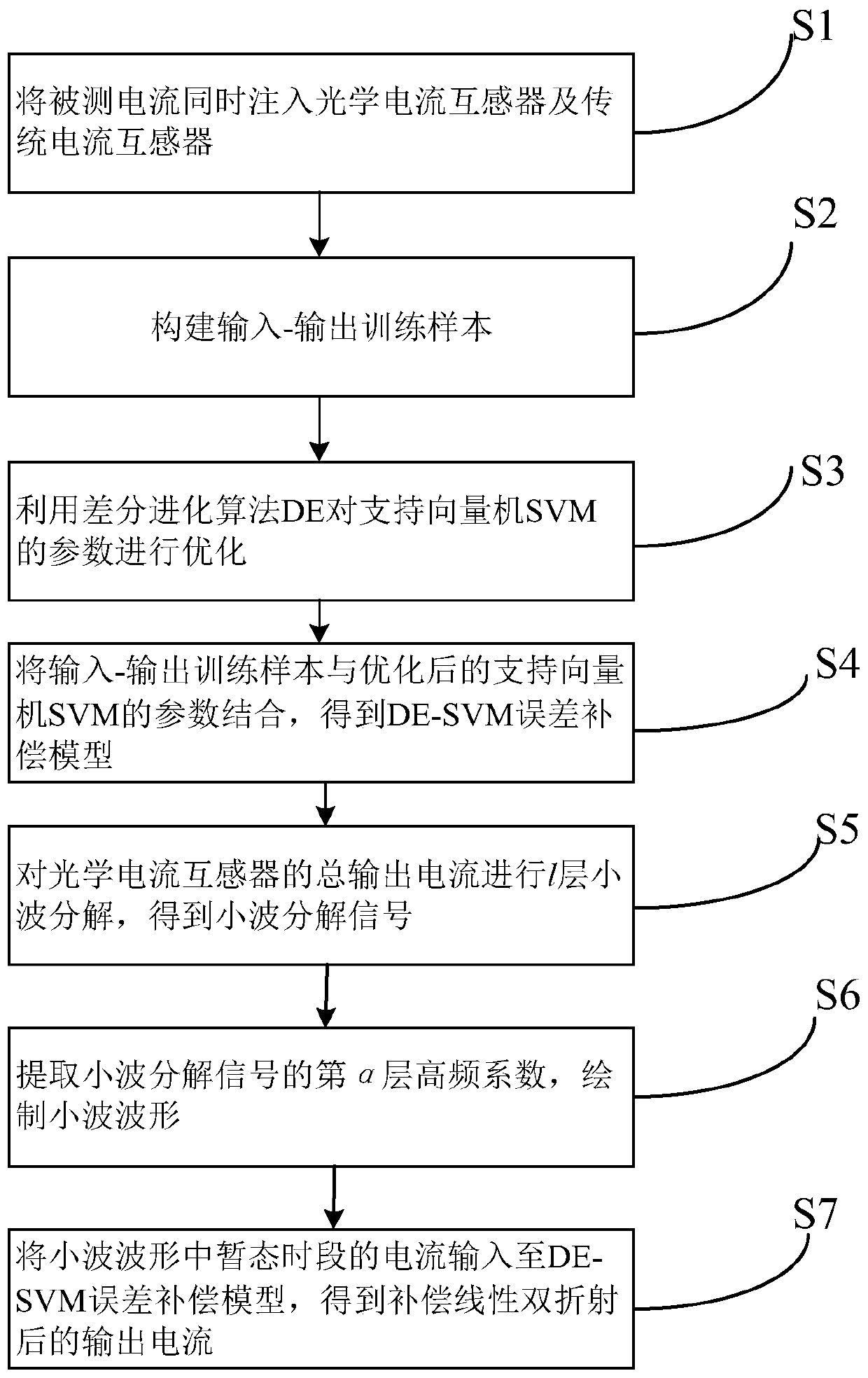
[0076] Such as figure 1 The flow chart of the DE-SVM-based optical current transformer error compensation method shown, the method includes the following steps:

[0077] S1. Inject the measured current into the optical current transformer and the traditional current transformer at the same time;

[0078] S2. The steady-state output current of the optical current transformer x i As an input training sample for error compensation, the output current y of the traditional current transformer at the same time i As an output training sample for error compensation, it forms an input-output training sample set i represents the i-th training sample, n represents the number of training samples;

[0079] S3. Select the support vector machine SVM, and use the differential evolution algorithm DE to optimize the penalty parameter C, the insensitive loss parameter ε and the kernel parameter σ of the support vector machine SVM; the penalty parameter c and the insensitive loss parameter ε ...


PUM


Abstract

The invention provides an optical current transformer error compensation method based on DE-SVM. The optical current transformer error compensation method comprises the following steps of: injecting ameasured current into an optical current transformer and a traditional current transformer at the same time; constructing an input-output training sample; optimizing parameters of an SVM (Support Vector Machine) by utilizing a DE (Differential Evolutionary Algorithm); combining the input-output training sample with the optimized parameters of the support vector machine SVM to obtain a DE-SVM error compensation model; carrying out l-layer wavelet decomposition on the output current of the optical current transformer to obtain wavelet decomposition signals; extracting an alpha-layer high-frequency coefficient of the wavelet decomposition signals, and drawing a wavelet waveform; and inputting the current in a transient state period in the wavelet waveform into the DE-SVM error compensation model to obtain a compensated output current. The optical current transformer error compensation method overcomes the defect that an existing complex mathematical model or algorithm is prone to fall into local optimum, does not need to transform the equipment, and is low in cost.

Description

technical field [0001] The present invention relates to the technical field of optical current transformer error compensation, and more specifically, relates to a DE-SVM-based optical current transformer error compensation method. Background technique [0002] Smart substation is an important part of smart grid, electronic transformer is the key equipment of smart substation, and all-fiber current transformer is one of the main varieties of electronic current transformer. Like the magneto-optic glass optical current transformer, the all-fiber current transformer is based on the Faraday magneto-optical effect, and has the advantages of no saturation, small size, simple insulation structure, corrosion resistance, aging resistance, and wide measurement range. It is an electronic current transformer. An important development direction of transformers. However, due to the residual linear birefringence in the optical fiber material, at the same time, various external factors such...

Claims


Application Information

Patent Timeline
Patent Type & Authority Applications(China)
IPC IPC(8): G01R35/02
CPCG01R35/02
Inventor 刘林戴航宋宇韦景康刘攸坚严杰峰包汉玲
Owner GUANGDONG POWER GRID CO LTD
Why Eureka
Try Eureka