A method and system for determining the sediment flux in the diversion channel and forebay of a pumping station

A technology for sediment and pumping stations, which is applied in the field of determination of sediment flux in the diversion channel and forebay of the pumping station, can solve the underestimation of the half-cycle average sediment flux, the inability to reflect the change of the moving bed surface and the effect of the moving bed surface, It cannot reflect the time response of sediment flux and other issues, so as to avoid the underestimation of sediment flux

Active Publication Date: 2022-02-08
CHINA AGRI UNIV
View PDF8 Cites 0 Cited by
  • Summary
  • Abstract
  • Description
  • Claims
  • Application Information

AI Technical Summary

Problems solved by technology

This leads to its disadvantages: it cannot reflect the change of the moving bed surface and the effect of the moving bed surface, it cannot reflect the time response of the sediment flux relative to the hydrodynamic conditions, and it cannot reflect the asymmetry of the boundary layer and the large phase difference. Negative net velocity and net flux will also cause an underestimation of the half-period average sediment flux
But so far, how to give the sediment flux of the sand-containing moving bed surface under the reciprocating flow conditions of the pumping station's diversion canal and the forebay, there is no achievement and method for reference. Therefore, the present invention continues to provide a pump Determination method of sediment flux in station diversion canal and forebay

Method used


Image

  • A method and system for determining the sediment flux in the diversion channel and forebay of a pumping station
  • A method and system for determining the sediment flux in the diversion channel and forebay of a pumping station
  • A method and system for determining the sediment flux in the diversion channel and forebay of a pumping station

Examples


Embodiment Construction

[0026] In order to make the purpose, technical solutions and advantages of the embodiments of the present invention clearer, the technical solutions in the embodiments of the present invention will be clearly described below in conjunction with the accompanying drawings in the embodiments of the present invention. Obviously, the described embodiments are the Some, but not all, embodiments are invented. Based on the embodiments of the present invention, all other embodiments obtained by persons of ordinary skill in the art without making creative efforts belong to the protection scope of the present invention.

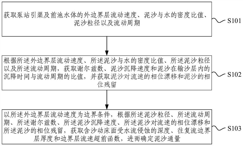
[0027] figure 1 A flow chart of a method for determining the sediment flux of a pumping station diversion channel and forebay provided by an embodiment of the present invention, including:

[0028] S101, obtaining the flow velocity of the outer boundary layer of the water body of the pumping station diversion channel and the forebay, the density ratio of the sediment t...


PUM


Abstract

The embodiment of the present invention provides a method for determining the sediment flux in the diversion channel of the pumping station and the forebay, wherein the method includes: obtaining the Shields number, the sedimentation velocity, and the sedimentation time and flow of the sediment in the sand transport layer The ratio of the period, and obtain the phase drift of the sediment to the flow velocity and the phase residue of the sediment; the flow velocity of the outer boundary layer is used as the boundary condition, according to the sediment particle size, flow period, Shields number, sediment settlement velocity, sediment For the phase drift of the flow velocity and the phase residue of the sediment, the depth of the sandy bed surface eroded by the water flow, the thickness of the reciprocating boundary layer and the advance function of the boundary layer velocity are obtained, and then the sediment flux is determined. Through the design and calculation of the determined relevant phase difference, dynamic bed surface and boundary layer thickness parameters, it can reflect the time response of the instantaneous sediment flux in the process of reciprocating flow relative to the hydrodynamic conditions, and reflect the changes of the dynamic bed surface and Moving bed surface effect, to avoid the underestimation of the half-period average sediment flux.

Description

technical field [0001] The embodiments of the present invention relate to the technical field of water conservancy engineering, and more specifically, to a method and system for determining the sediment flux of a pumping station diversion channel and a forebay. Background technique [0002] Sediment flux is the product of sediment concentration and velocity, indicating the amount of sediment passing through a unit section per unit time. In the reciprocating flow of the pumping station's diversion channel and the sandy bed surface of the forebay, the sediment flux is dynamically changing . [0003] The sediment flux widely used in engineering is derived based on the theory of constant flow, without considering the change of the moving bed surface, and does not include the asymmetry and phase difference of the boundary layer. This leads to its disadvantages: it cannot reflect the change of the moving bed surface and the effect of the moving bed surface, it cannot reflect the ...

Claims


Application Information

Patent Timeline
Patent Type & Authority Patents(China)
IPC IPC(8): G06F30/20G06F17/11
CPCG06F17/11
Inventor 陈鑫汤远王福军胡昕宇
Owner CHINA AGRI UNIV
Why Eureka
Try Eureka