An automatic crimping machine for electronic components

A technology of electronic components and crimping machines, which is applied in the direction of electrical components, circuit/collector components, connections, etc., can solve the problem that multiple processes cannot be realized at the same time, the fixed connection between terminals and wires is not reliable, and the wire pressure cannot be guaranteed. In order to achieve the effect of reducing the probability of insufficient fixation, improving convenience, and reducing the difficulty of control

Active Publication Date: 2021-03-16
贵州芯火悦创科技有限公司
View PDF6 Cites 0 Cited by
  • Summary
  • Abstract
  • Description
  • Claims
  • Application Information

AI Technical Summary

Problems solved by technology

[0003] When fixing the terminal on one end of the wire, it is necessary to peel one end of the wire and cut it after reaching a certain length, and then transport it to the jaws of the clamping tool for crimping. During this process, the clamping tool keeps holding The wires are clamped, and multiple processes cannot be realized at the same time, which makes the production efficiency extremely low. Similarly, in the patent No. 201621381968.4, grooves are set on the annular table surface, and the cut and peeled wires are used Prevent it from being in it, then rotate it, socket the terminal in turn, and then crimp it, but when the wire is on the ring-shaped table, there is no fixing device and it is easy to slide, especially when it is socketed with the terminal, once the wire shifts, the terminal If the socket with the wire is not sufficient, the subsequent crimping will not be reliable, and the terminal will easily fall off, which will affect the product quality
[0004] The crimping machine uses the jaws to crimp the terminals, but when the jaws are crimping, the crimping starts from the inside of the jaws, and as the jaws are closed, the jaws that first contact the terminals continue to punch the terminals , but it hinders the coverage of the subsequent jaws, and the crimping height of the wire cannot be guaranteed (the crimping height refers to the cross-sectional height of the crimping area of ​​the wire after crimping), so that the stamping force on the terminal is not enough. Uniformity will cause the fixed connection between the terminal and the wire to be unreliable and reduce the rated current of the wire. At the same time, it will also cause the performance of the crimping area to decrease under abnormal working conditions. Too small crimping height will also break the wire of the wire. core or break off the metal in the crimping area of ​​the wire

Method used


Image

  • An automatic crimping machine for electronic components
  • An automatic crimping machine for electronic components
  • An automatic crimping machine for electronic components

Examples


Embodiment Construction

[0021] The following will clearly and completely describe the technical solutions in the embodiments of the present invention with reference to the accompanying drawings in the embodiments of the present invention. Obviously, the described embodiments are only some, not all, embodiments of the present invention. Based on the embodiments of the present invention, all other embodiments obtained by persons of ordinary skill in the art without making creative efforts belong to the protection scope of the present invention.

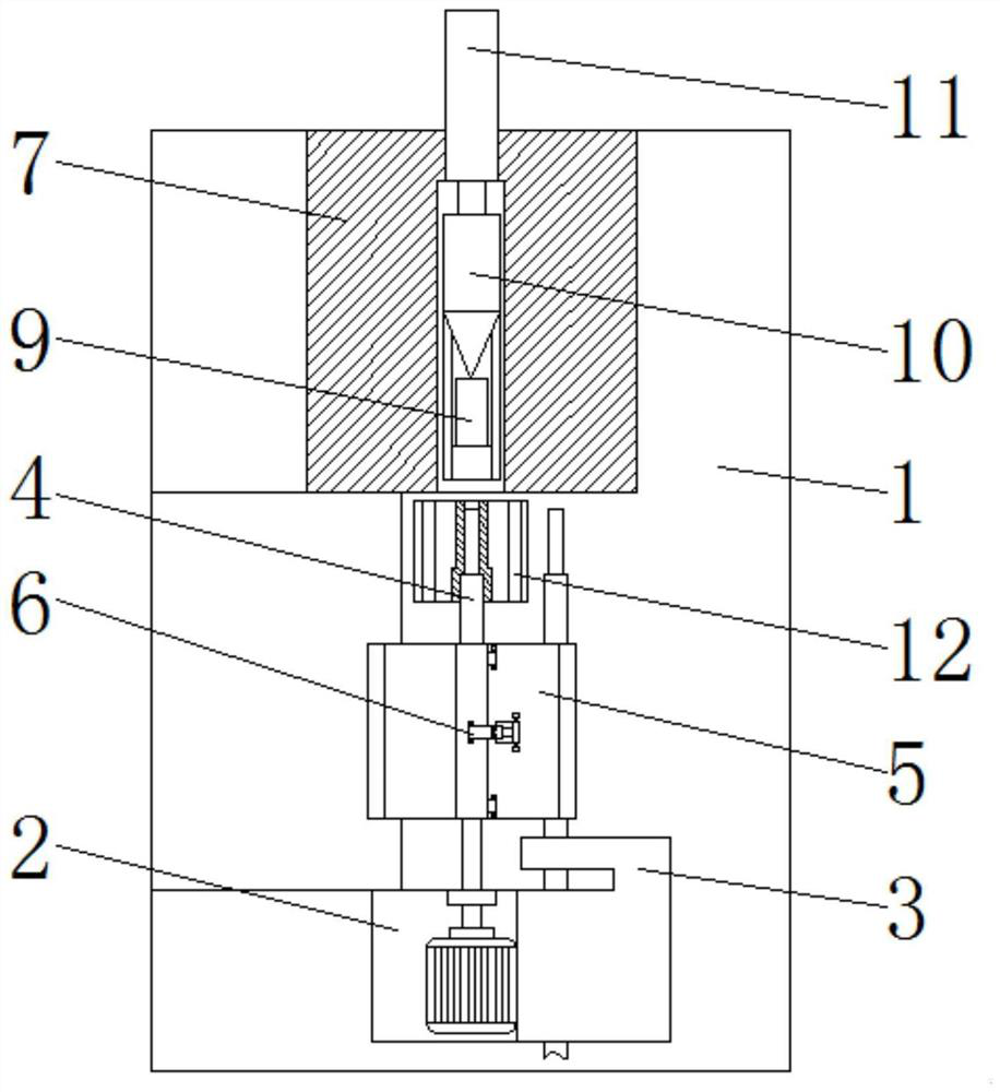
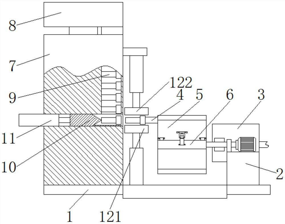
[0022] see Figure 1-5 , an automatic crimping machine for electronic components, comprising a base 1, a fixing seat 2 is fixedly installed on the front part of the upper surface of the base 1, a cable processing device 3 is fixedly installed on the top right side of the fixing seat 2, and a cable processing device 3 is fixedly installed on the upper surface of the base 1 The support frame 7 is fixedly installed on the back, the terminal arrangement disk 8 is ...


PUM


Abstract

The invention relates to the technical field of electronic component crimping equipment, and discloses an automatic crimping machine for electronic components. The automatic crimping machine comprisesa base, wherein a fixed seat is fixedly mounted at the front part of the upper surface of the base, and a cable processing device is fixedly mounted at the top of the right side of the fixed seat. The processing process of a wire is divided into four areas through the arrangement of a square rotating body and a fixing device, so that the cutting, peeling and crimping of the connecting terminal and the releasing process of the wire can be simultaneously performed, and the production efficiency of the crimping machine is greatly improved. In addition, the equipment operation control difficultyis reduced through the fixed rotation angle, the positioning accuracy between the wire and the connecting terminal is improved, and the product production quality is improved. Meanwhile, the wire is fixed by the fixing device, the wire is prevented from moving when the connecting terminal is fixed by sleeving and stamping, the wire is further prevented from being inserted into the connecting terminal too deeply or too shallowly, and the probability of insufficient fixation of the connecting terminal is reduced.

Description

technical field [0001] The invention relates to the technical field of crimping equipment for electronic components, in particular to an automatic crimping machine for electronic components. Background technique [0002] Terminal block is an accessory product used to realize electrical connection, which belongs to the category of connectors. At the same time, with the increasing degree of industrial automation and stricter and more precise industrial control requirements, the amount of terminal blocks is gradually increasing, and With the development of the electronics industry, the use of terminal blocks is becoming wider and wider. In order to facilitate electrical connection, terminal blocks are often used to connect one end or both ends of the wires. At present, crimping machines are often used to connect terminal blocks and wire joints. Stamping is carried out, but there are some deficiencies in the existing crimping machine during use, as follows; [0003] When fixing...

Claims


Application Information

Patent Timeline
Patent Type & Authority Patents(China)
IPC IPC(8): H01R43/048H01R43/05
CPCH01R43/048H01R43/05
Inventor 陈海南
Owner 贵州芯火悦创科技有限公司
Why Eureka
Try Eureka