Difference frequency type high-frequency motor
A differential frequency, high-frequency current technology, used in motor control, asynchronous generator control, AC motor control, etc., can solve the problems of large consumption of coil electromagnetic materials, inconvenient installation and transportation, and high manufacturing costs, and achieve manufacturing costs. The effect of reducing, convenient power transmission, and cost reduction
- Summary
- Abstract
- Description
- Claims
- Application Information
AI Technical Summary
Problems solved by technology
Method used
Image

Examples
Embodiment 1
[0036] Example 1: When used as a high-frequency motor:
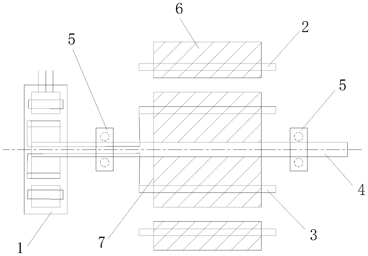
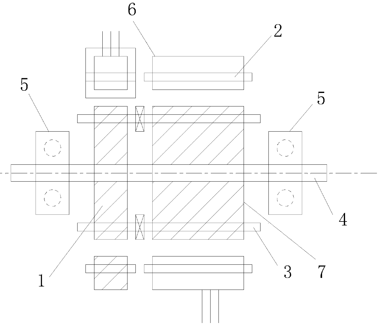
[0037] A differential frequency high-frequency motor, further comprising a high-frequency excitation generator 1, the high-frequency excitation generator 1 is connected to the rotor coil 3, and the high-frequency excitation generator 1 is input with two-phase or three-phase Low-power high-frequency current, the output high-frequency excitation current is input into the rotor coil 3, so that the rotor generates a high-speed rotating magnetic field, and a two-phase or three-phase current higher or lower than the excitation frequency is passed into the stator coil, so that the stator Generate a rotating magnetic field that rotates in the same direction as the rotor;
[0038] When the stator frequency is higher than the rotor frequency, the rotor will rotate in the same direction of the rotating magnetic field, and the rotor outputs a speed at the difference between the two frequencies, and the speed is positively correlated...
Embodiment 2
[0044] Example 2: When used as a high frequency generator:
[0045] A differential frequency high-frequency motor, further comprising a high-frequency excitation generator 1, the high-frequency excitation generator 1 is connected to the rotor coil 3, and the high-frequency excitation generator 1 is input with two-phase or three-phase Low-power high-frequency current, the output high-frequency excitation current is input into the rotor coil 3, so that the rotor generates a high-speed rotating magnetic field, and at the same time, the power source is connected to the drive shaft to provide mechanical energy for the rotor;
[0046] If the exciting rotating magnetic field is opposite to the rotor turning direction, so that the rotor coil cuts the magnetic field lines to generate current, the excitation frequency plus the rotor speed frequency is generated in the rotor coil. As long as the magnetic field of the excitation generator rotates in the same direction as the rotating magn...
Embodiment 3
[0059] Example 3: When a high-frequency generator is used in combination with a high-frequency motor:
[0060] A differential frequency high-frequency motor, further comprising a high-frequency excitation generator 1, the high-frequency excitation generator 1 is connected to the rotor coil 3, and the high-frequency excitation generator 1 is input with two-phase or three-phase Low-power high-frequency current, the output high-frequency excitation current is input into the rotor coil 3, so that the rotor generates a high-speed rotating magnetic field, and at the same time, a power source is connected to the drive shaft to provide mechanical energy for the rotor, at this time, the high-frequency motor realizes the generator function; This high-frequency generator is provided with two sets of stator windings, and the two sets of stator coils output two or more generators with different frequency potentials due to the different connection methods of the rotor coils;
[0061] The tw...
PUM
 Abstract
Description
Claims
Application Information
 - R&D Engineer
- R&D Manager
- IP Professional
- Industry Leading Data Capabilities
- Powerful AI technology
- Patent DNA Extraction
Browse by: Latest US Patents, China's latest patents, Technical Efficacy Thesaurus, Application Domain, Technology Topic.
© 2024 PatSnap. All rights reserved.Legal|Privacy policy|Modern Slavery Act Transparency Statement|Sitemap