

A self-driven synchronous rectification circuit for forward converter
Patent Information
- Authority / Receiving Office
- CN · China
- Patent Type
- Patents(China)
- Current Assignee / Owner
- 河南嘉晨智能控制股份有限公司
- Publication Date
- 2022-04-29
Smart Images
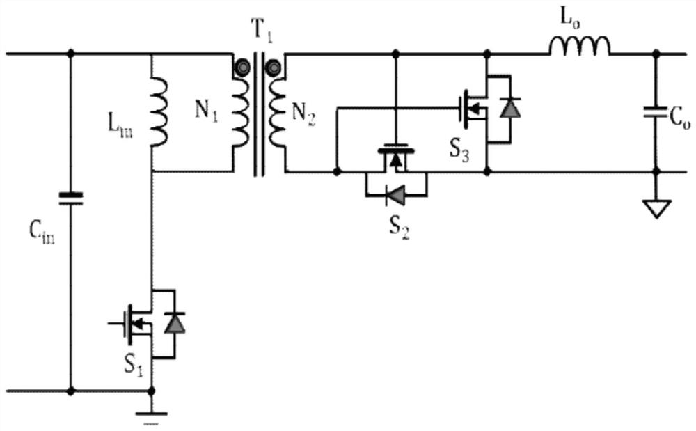
Figure 1 
Figure 2 
Figure 3
Abstract
Description
technical field
[0001] The invention provides a self-driven synchronous rectification circuit, which belongs to the field of drive circuits. In particular, it relates to a drive circuit for a forward converter. Background technique
[0002] A synchronous rectification circuit of an existing forward converter such as figure 1 shown. The circuit includes: transformer T1, first MOS transistor S1, second MOS transistor S2, third MOS transistor S3, output inductor L O , output capacitance C O and the input capacitor C in . The connection relationship of each electronic component is as follows figure 1 As shown, the input signal generates a changing current in the primary side winding N1 of the transformer T1 through the turn-on and turn-off of the first MOS transistor S1, and the power is transmitted to the secondary side circuit through the primary side winding N2 of the transformer T1. The third MOS transistor S3 serving as a rectifier and the second MOS transistor S2 se...