
Wide surface processing and shot-blasting mechanism

A technology of wide surface and shot blasting chamber, which is applied to the processing device of used abrasives, grinding/polishing equipment, abrasives, etc. It can solve the problems of low processing efficiency, rollover, and the failure of the whole machine to improve efficiency. , increase the width, reduce the effect of difficulty

Pending Publication Date: 2020-06-19
成都蜀工机械制造有限公司
View PDF1 Cites 1 Cited by
  • Summary
  • Abstract
  • Description
  • Claims
  • Application Information

AI Technical Summary

Problems solved by technology

However, we have found in actual work that this horizontal movement design has almost no practical significance, and because of this design, the whole machine cannot handle the position near the wall or the corner (there is always a large gap between the processing surface and the wall) Otherwise, the driving and power unit of the whole machine will be too close to the wall, which will easily cause safety hazards such as rollover), and there are obvious limitations in use.
Therefore, combined with the design concepts in the existing technology, we designed a new shot blasting mechanism for processing large-area surfaces of large buildings to solve the problems of small and medium-sized shot blasting equipment with small processing areas and low processing efficiency. , At the same time, it also overcomes the problem that the current large-scale vehicle-mounted shot blasting mechanism cannot handle the position close to the wall or corner

Method used


Image

  • Wide surface processing and shot-blasting mechanism
  • Wide surface processing and shot-blasting mechanism
  • Wide surface processing and shot-blasting mechanism

Examples


Embodiment

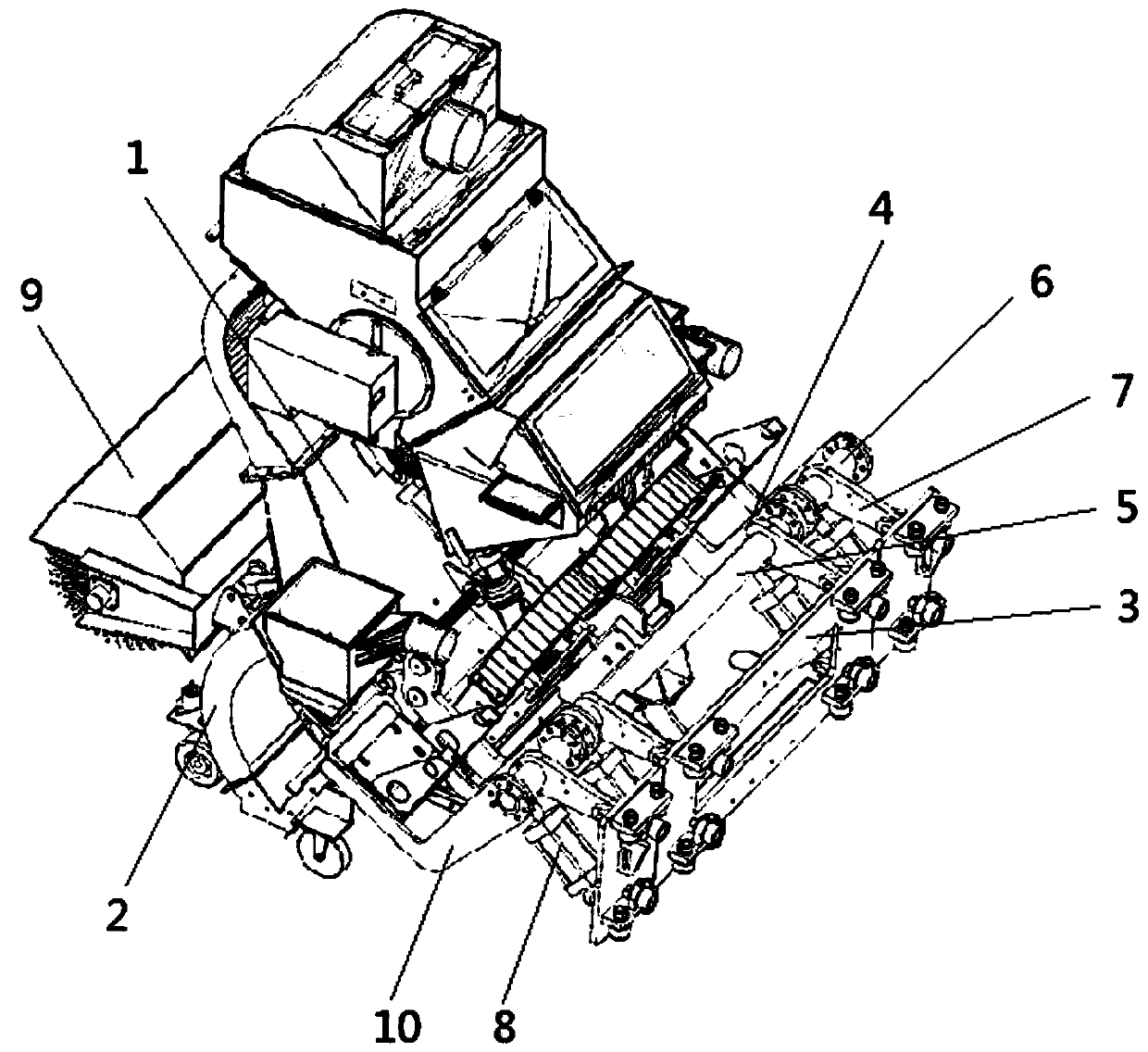
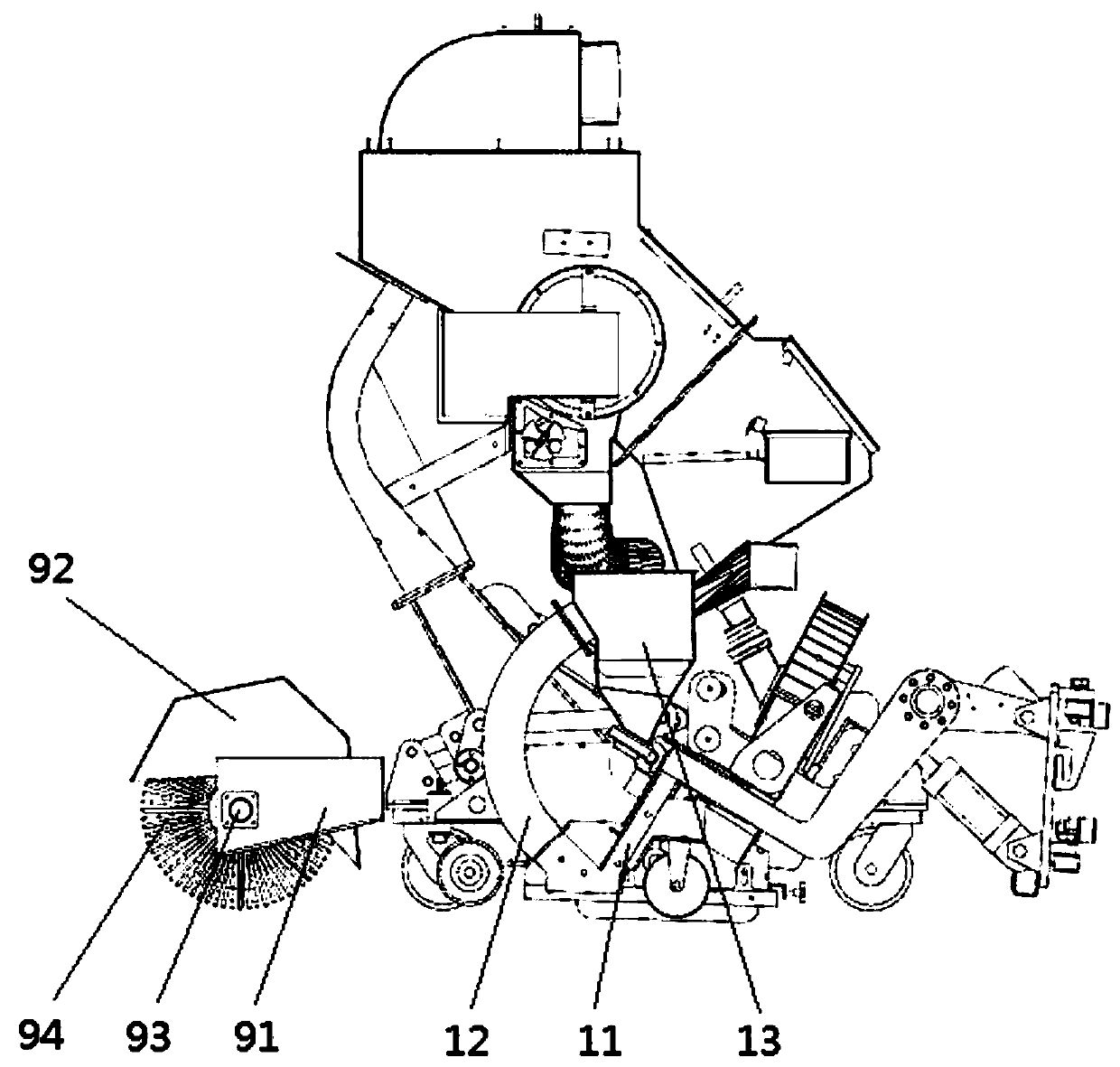
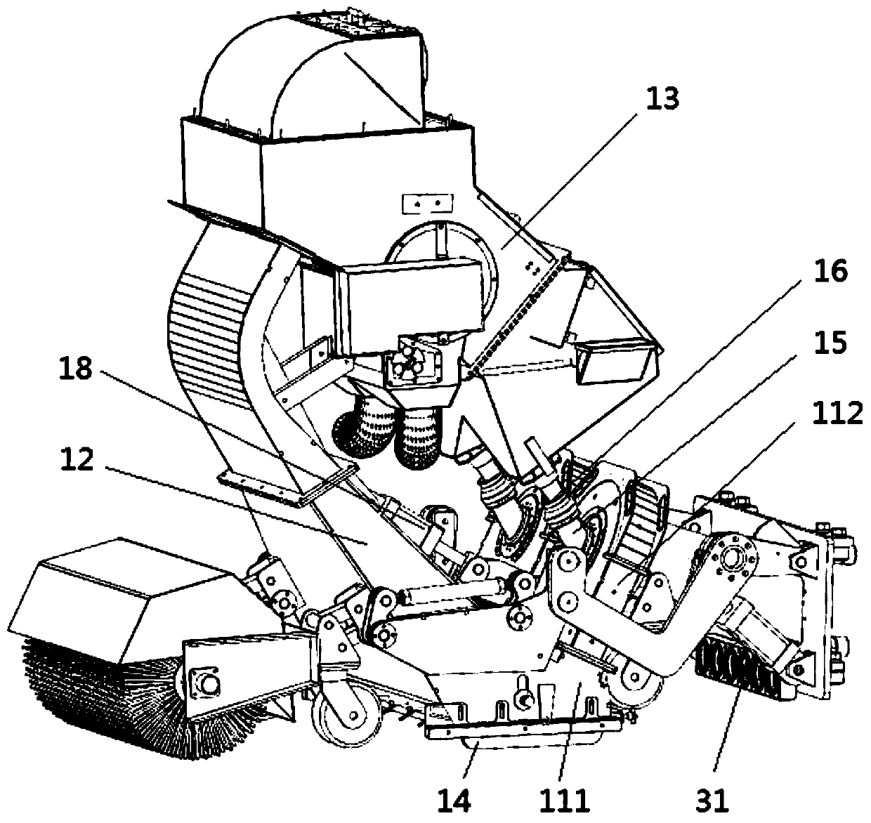
[0032] See attached figure 1 The wide-surface processing shot blasting mechanism provided in this embodiment includes a mounting frame, a main shot blasting unit 1 and at least one set of side shot blasting units 2. A set of side shot blasting units 2 and a set of main shot blasting units 1 are connected to each other through the mounting frame The power unit connection can also achieve the purpose of greatly increasing the processing area and processing surfaces close to the wall or corner. Compared with the existing vehicle-mounted front-side shot blasting mechanism, which only has the form of the main shot blasting unit, it not only removes the meaningless side shift unit structure, but also ensures the more reliable rigidity between the front-end main and side shot blasting units and the whole machine. Connection to prevent large leakage of steel shots during work due to unstable connection, and the combination of the side shot blasting unit 2 and the main shot blasting unit...


PUM


Abstract

The invention discloses a wide surface processing and shot-blasting mechanism. The wide surface processing and shot-blasting mechanism comprises a mounting frame, a main shot-blasting unit and at least one group of shot-blasting units, wherein the mounting frame comprises a connecting plate, a main connector for connecting the main shot-blasting unit and enabling the front end of the main shot-blasting unit to warp up or droop and a side connector for connecting the side shot-blasting unit and enabling the front end of the side shot-blasting unit to warp up or droop; the main connector comprises a main transverse shaft, two main connecting arms which are fixedly connected to the main transverse shaft and at least one group of first power assemblies which are connected to the main transverse shaft; the two main connecting arms are separately fixedly connected to the two sides of the main shot-blasting unit; the side connector comprises a side transverse shaft, at least one side connecting arm and at least one group of second power assemblies; and at least one side connecting arm is connected between the side shot-basting unit and the side transverse shaft. The wide surface processing and shot-blasting mechanism can increase the width of a processed surface, and can process a concrete or steel structure surface which is close to a wall surface (vertical surface) or close to a corner.

Description

Technical field [0001] The invention relates to the technical field of surface shot blasting treatment, in particular to a wide surface treatment shot blasting mechanism. Background technique [0002] For some large-scale building concrete surface and steel structure surface shot blasting operations, multiple small or medium-sized mobile shot blasting equipment are required to work together. Because these mobile shot blasting equipment have a small processing surface, the overall processing efficiency is It is relatively low, so it is necessary to design a large-scale integrated shot blasting equipment to cope with the large-area surface shot blasting operations of large buildings. [0003] In the prior art, the Chinese invention patent with application number 201310476180.6 discloses a cab shot blasting machine. As a large-scale shot blasting equipment with a walking system, it can deal with large-area large-area surfaces of large-scale buildings with high efficiency. Shot blasti...

Claims


Application Information

Patent Timeline
Patent Type & Authority Applications(China)
IPC IPC(8): B24C1/10B24C5/00B24C9/00
CPCB24C1/10B24C5/00B24C9/006
Inventor 秦昌伟
Owner 成都蜀工机械制造有限公司
Learn More