
Printing process for cosmetic packaging bottle cap

A technology for packaging bottle caps and cosmetics. It is applied in printing, printing machines, rotary printing machines, etc. It can solve the problems that affect the formation of patterns and characters, and the slow speed of solidification and drying, so as to achieve faster curing speed, long service life and good adhesion. effect of effect

Active Publication Date: 2020-06-19
SHANGYU TIANQIN PACKAGING
View PDF6 Cites 2 Cited by
  • Summary
  • Abstract
  • Description
  • Claims
  • Application Information

AI Technical Summary

Problems solved by technology

[0005] However, after the bottle cap is printed with a pattern or text, the cylinder drives the bottle cap to move from close to the screen printing screen to away from the screen printing screen. Since the ink has just been printed on the bottle cap, the ink solidifies and dries slowly. The ink is in a wet state, and when the staff removes the cap from the plug-in post, they will accidentally touch the pattern and text on the cap, thus affecting the formation of the pattern and text

Method used

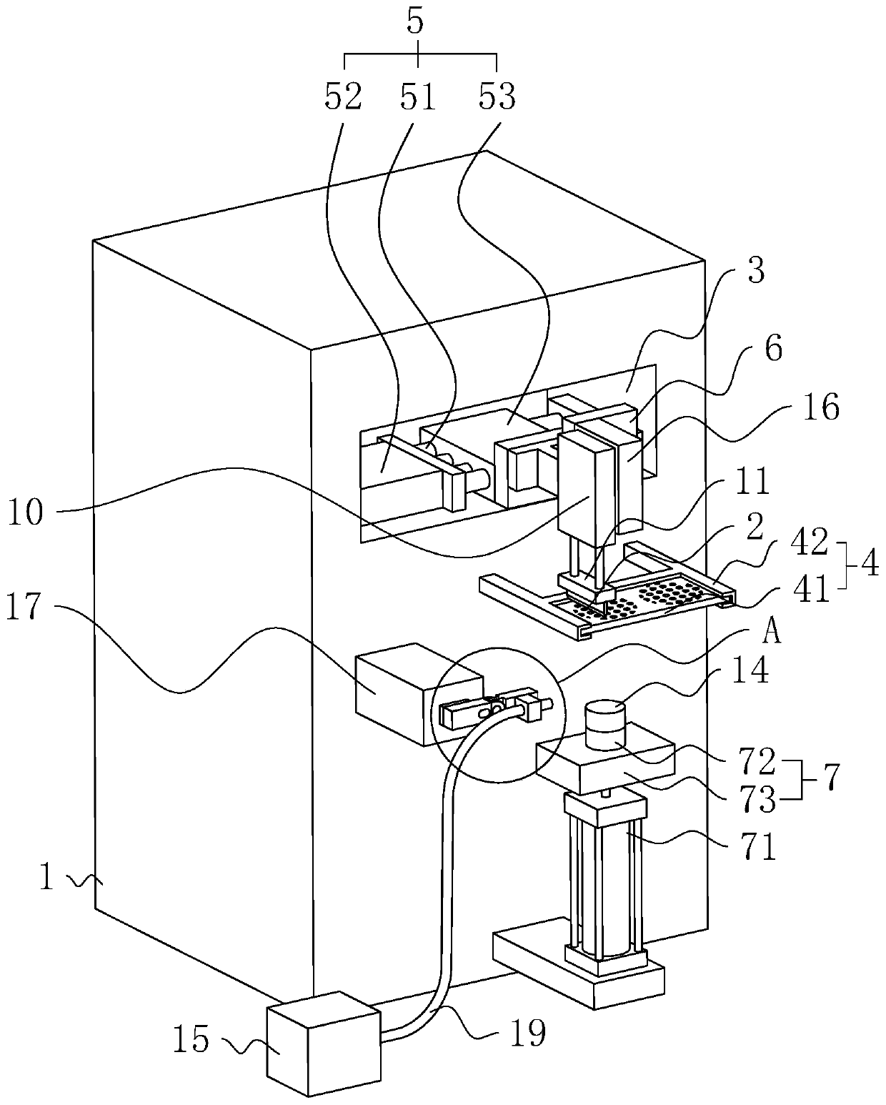

Image

  • Printing process for cosmetic packaging bottle cap
  • Printing process for cosmetic packaging bottle cap
  • Printing process for cosmetic packaging bottle cap

Examples


Embodiment 1

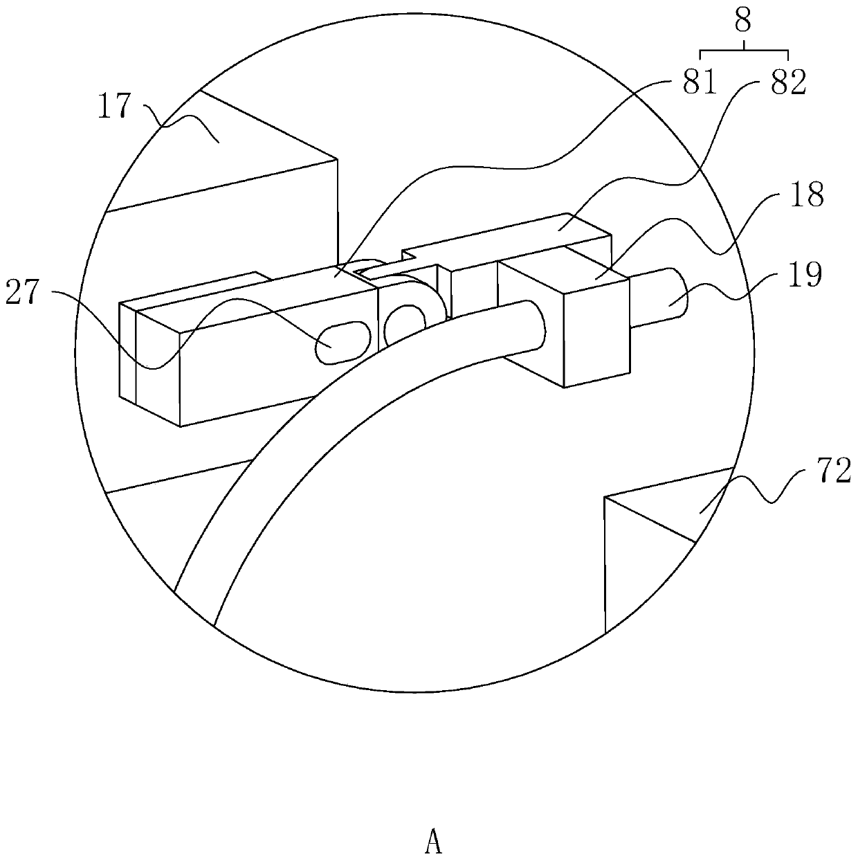
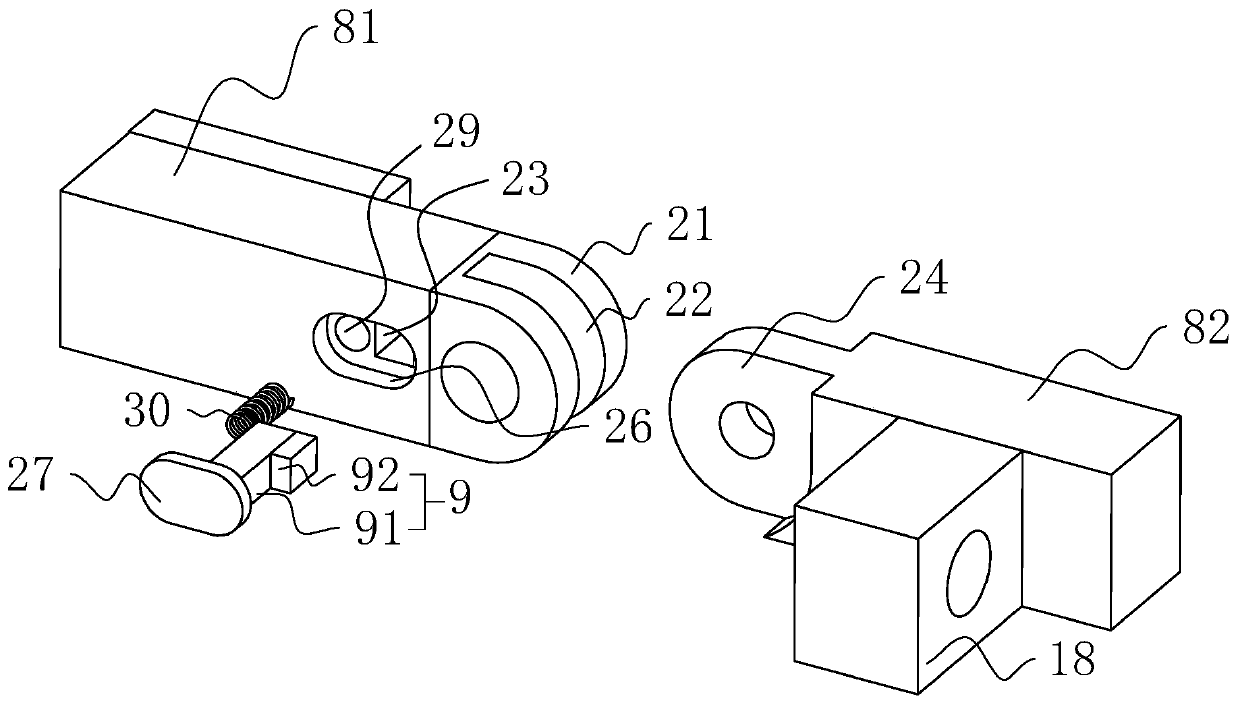
[0046] refer to figure 1 , a printing process for cosmetic packaging bottle caps, all steps are carried out on a flat screen screen printing machine. A flat screen screen printing machine includes a machine body 1. A printing assembly 4 is arranged on the side wall of the machine body 1 , and the printing assembly 4 includes a fixing bracket 41 and a screen printing screen 42 . The fixed bracket 41 is fixedly arranged on the side wall of the machine body 1 , the screen printing screen 42 is arranged on the fixing bracket 41 , and a plurality of discharge holes are opened on the screen printing screen 42 . The shape of the screen printing screen 42 is rectangular, and the length direction of the screen printing screen 42 is parallel to the side wall of the body 1 on which the fixing bracket 41 is installed. The upper surface of the screen printing screen 42 is slidably provided with a screen printing scraper 2 along the length direction. The screen printing scraper 2 is driv...

Embodiment 2

[0062] The difference between this embodiment and Embodiment 1 lies in: S4: post-processing the bottle cap 14 after the treatment in S3. The post-processing process is that the staff use a brush to soak the protective agent. The raw materials of the protective agent include 40 parts of silica sol, 22 parts of toluenesulfonamide-formaldehyde resin, 2.5 parts of m-xylylenediamine and ethanolamine acetate in parts by weight. 24 servings. The staff uses a brush soaked in protective agent to apply protective agent to the graphic layer after S3 treatment. After the protective agent is evenly applied, the staff starts the blower 15 again to send hot air towards the upper surface of the bottle cap 14, so that the upper surface of the bottle cap 14 is kept at 70°C, and blows continuously for 4 minutes, and then the staff removes the bottle cap 14 from the plug post 72 and unplug it.

[0063] The difference between Examples 3-6 and Example 2 is that the raw materials of the protective...


PUM

PropertyMeasurementUnit
sedimentation rateaaaaaaaaaa

Abstract

The invention relates to the technical field of printing, and discloses a printing process for a cosmetic packaging bottle cap. The process is characterized in that the prepared bottle cap is subjected to the following procedures of S1, clearing sundries on the bottle cap; S2, printing printing ink on the bottle cap treated in the step S1; S3, drying the part, containing the printing ink, of the bottle cap treated in the S2; S4, carrying out post-treatment on the bottle cap treated in the step S3; and finishing printing the bottle cap after the treatment in S4. According to the process, afterthe printing ink is printed on the bottle cap, the printing ink is dried, so that the drying speed of the printing ink is increased; and with the increase of the drying speed of the printing ink, theinfluence of workers on the printing ink printed on the bottle cap is reduced, and then the bottle cap printing quality is ensured.

Description

technical field [0001] The invention relates to the technical field of printing, more specifically, it relates to a printing process for cosmetic packaging bottle caps. Background technique [0002] At present, cosmetic packaging bottles are becoming more and more abundant. In order to be able to play a role of identification and beauty, it is usually necessary to print patterns or words on the body and cap of cosmetic packaging bottles to achieve publicity and aesthetic effects. Existing equipment used when printing patterns or characters on bottle caps is a screen printing machine. [0003] For example, the Chinese patent whose authorized announcement number is CN204123759U discloses a kind of anti-static screen printing machine, which includes a workbench, a fixed support, a screen printing plate and a movable arm. The control panel is used to adjust the operating parameters of the printing machine. The screen printing base is fixedly installed between the two conveyor b...

Claims


Application Information

Patent Timeline
Patent Type & Authority Applications(China)
IPC IPC(8): B41M1/12B41M1/26B41M7/00B41F15/12B41F15/18B41F15/36B41F15/44
CPCB41F15/12B41F15/18B41F15/36B41F15/44B41M1/12B41M1/26B41M7/0054B41M7/009
Inventor 郦奇男杨赟
Owner SHANGYU TIANQIN PACKAGING
Learn More