
Yoke end assembly, transmission module, electromechanical braking device, braking clamp unit and rail vehicle

A brake device and brake caliper technology, which is applied in the field of rail vehicles, can solve problems such as uneven mass distribution and difficulty in accurately controlling braking force, and achieve the effects of avoiding adverse effects, reasonable structure and functional layout, and easy assembly

Pending Publication Date: 2020-06-19
CRRC CHANGZHOU TECH MARK IND CO LTD +1
View PDF0 Cites 0 Cited by
  • Summary
  • Abstract
  • Description
  • Claims
  • Application Information

AI Technical Summary

Problems solved by technology

[0003] However, the mass distribution of existing electromechanical braking devices is extremely uneven, making it difficult to accurately control the output braking force

Method used


Image

  • Yoke end assembly, transmission module, electromechanical braking device, braking clamp unit and rail vehicle
  • Yoke end assembly, transmission module, electromechanical braking device, braking clamp unit and rail vehicle
  • Yoke end assembly, transmission module, electromechanical braking device, braking clamp unit and rail vehicle

Examples


no. 1 example

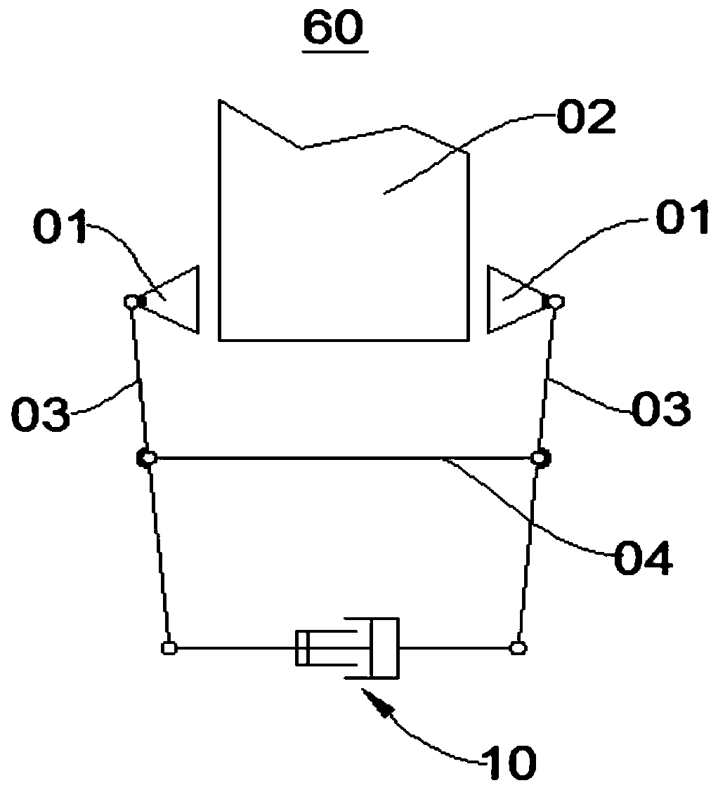
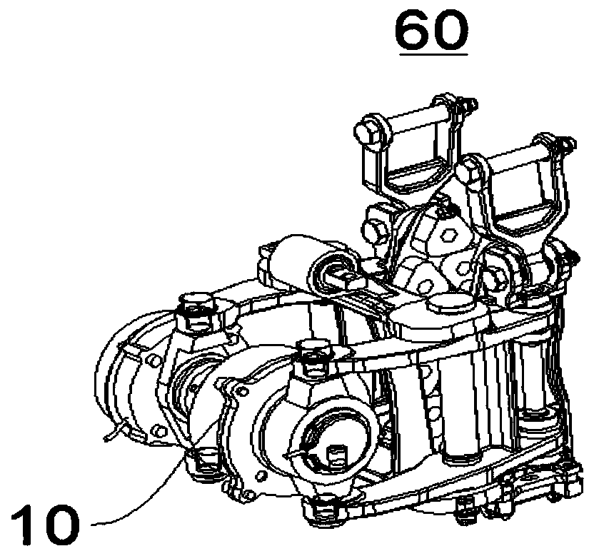
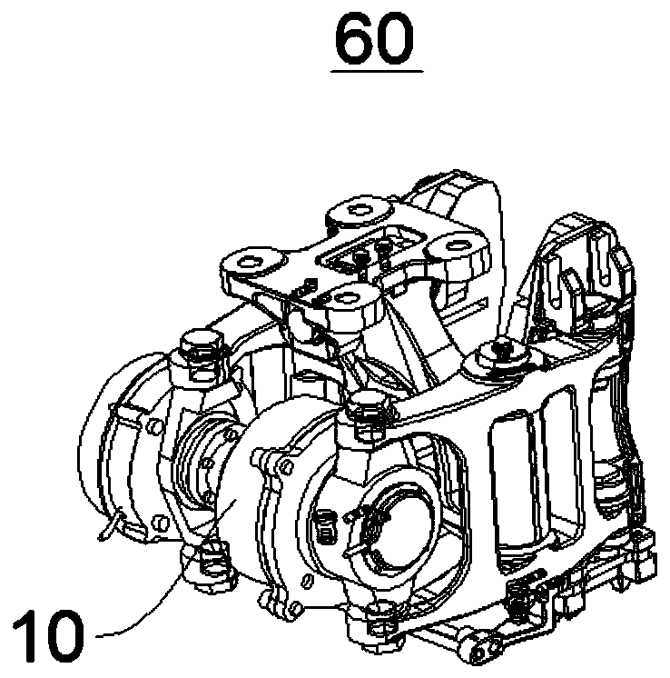
[0091] Please refer to figure 1 , the present embodiment provides a brake caliper unit 60, which can be used in a rail vehicle to brake or release the brake of the rail vehicle. The brake caliper unit 60 can be a three-point suspension brake caliper unit (see figure 2 ) or four-point suspension brake caliper unit (see image 3 ).

[0092] The brake caliper unit 60 includes a brake caliper and an electromechanical brake device 10. The electromechanical brake device 10 is connected to the brake caliper in transmission and is used to drive the brake caliper to brake or release the brake on the rail vehicle. move.

[0093] In detail, the brake caliper includes a brake pad holder 01 , a lever 03 and a hanger 04 . The two opposite ends of the electromechanical braking device 10 are respectively hinged to the first ends of the levers 03 on both sides. When the electromechanical braking device 10 is extended or shortened, the braking force or releasing braking force output by th...

no. 2 example

[0139] Please refer to Figure 18 , the present embodiment provides a brake caliper unit 60 whose overall structure, working principle and technical effects are similar to those of the first embodiment, except that the drive module 20 of the electromechanical braking device 10 and the yoke end The concrete structure of assembly 40 is introduced in detail below:

[0140] For driver module 20, please refer to Figure 19 and Figure 20 , in this embodiment, the housing 100 of the driving module 20 includes a front cover 140 and a rear cover 150 connected to each other, the front cover 140 is roughly cylindrical, and the inner wall and the outer wall of the rear cover 150 have stepped steps with gradually smaller diameters. , one end of the rear cover 150 is connected to the front cover 140, and the other end is provided with a mounting hole and an end cover 160 for opening and closing the mounting hole. A first step 152 and a second step 154 ​​are disposed on the inner periphe...


PUM


Abstract

The embodiment of the invention provides a yoke end assembly, a transmission module, an electromechanical braking device, a braking clamp unit and a rail vehicle and relates to the technical field ofbraking. The electromechanical braking device adjusts the position of a power-losing locking mechanism, the electromechanical braking device is matched with a braking yoke to form a new yoke end assembly, so the whole electromechanical braking device is more reasonable in structure and function layout and more balanced in mass distribution, the braking force outputted by the electromechanical braking device can be accurately controlled, operation is more stable and reliable, moreover, assembly, disassembly and fault detection are further facilitated. Correspondingly, a braking clamp unit adopting the electromechanical braking device and a rail vehicle are more stable and reliable during running.

Description

technical field [0001] The invention relates to the technical field of braking, in particular to a yoke end assembly, a transmission module, an electromechanical braking device, a brake caliper unit and a rail vehicle. Background technique [0002] In the field of vehicle braking technology, especially in the field of rail transit braking technology, the braking system has mainly experienced through brakes, automatic brakes, through automatic brakes, electro-pneumatic brakes, computer-controlled through-electric-pneumatic Stages of development of braking systems. With the development of science and technology, electromechanical braking devices have gradually appeared on the market. The electromechanical brake device uses electric energy to directly drive the brake pads to rub against the brake disc (wheel tread), and then converts the kinetic energy of the vehicle into heat energy to produce a braking effect. [0003] However, the mass distribution of the existing electrom...

Claims


Application Information

Patent Timeline
Patent Type & Authority Applications(China)
IPC IPC(8): B60T13/74H02K7/102B61H11/00
CPCB60T13/748B60T13/746H02K7/1021B61H11/00
Inventor 鲍春光苟青炳杜利清王睿文曾梁彬韩红文
Owner CRRC CHANGZHOU TECH MARK IND CO LTD
Learn More