Automatic machine tool cutting fluid recovery processor

A cutting fluid and processor technology, applied in lubricating compositions and other directions, can solve the problems of increased cutting fluid consumption cost, bacterial proliferation, waste of cutting fluid resources, etc., and achieve the effect of reducing enterprise cost consumption, simplifying recycling process, and saving resources

Pending Publication Date: 2020-06-19
XUZHOU OUBAI RUI INTELLIGENT EQUIP CO LTD
View PDF5 Cites 0 Cited by
  • Summary
  • Abstract
  • Description
  • Claims
  • Application Information

AI Technical Summary

Problems solved by technology

[0002] Cutting fluid is an industrial liquid used in metal cutting and grinding to cool and lubricate cutting tools and workpieces. Cooling performance, lubricating performance, anti-rust performance, degreasing and cleaning function, anti-corrosion function, easy to dilute, etc. After a period of use, the cutting fluid will be mixed with waste and impurities during processing, and at the same time due to The irregular operating habits of the workshop workers and their long-term non-use lead to the growth of bacteria in the cutting fluid, resulting in the deterioration of the cutting fluid and the phenomenon of "smelly". Traditionally, the treatment method for the deteriorated and smelly cutting fluid is to pump it out After adding new cutting fluid, the smelly cutting fluid cannot be processed in time and can only be sent back to the manufacturer for recycling, which leads to an increase in the cost of cutting fluid consumption and a waste of cutting fluid resources. The cutting fluid recovery device is mainly aimed at the separation of cutting fluid and solid impurities, and it cannot handle the smelly and deteriorated cutting fluid well.
[0003] The notification number CN210021403U discloses a cutting fluid recovery and separation device for PVC production equipment, including a cutting fluid recovery box and an oil-water separator, the cutting fluid recovery box is connected to the oil-water separator through a pipeline, and the cutting fluid recovery box There is a cutting fluid inlet on the top, and a filtering area, a cooling area, and a metal adsorption area are arranged in the cutting fluid recovery box. A filter plate is arranged in the filtering area, and a magnetic adsorption rod is arranged in the metal adsorption area. The cooling A cooling pipe is provided in the area, and one end of the cooling pipe communicates with the filter area, and the other end of the cooling pipe communicates with the metal adsorption area. The bottom of the oil-water separator is provided with an air blowing pump, and the air blowing pump is connected to the filter area in the oil-water separator. The air jet pipe is connected, the oil-water separator is also provided with a cross bar, and an induction device is provided on the cross bar, and a vertical rod is provided under the induction device, and a floating ball is provided on the vertical rod. The cutting fluid is subjected to solid-liquid separation treatment, and it is impossible to recycle the deteriorated cutting fluid

Method used


Image

  • Automatic machine tool cutting fluid recovery processor
  • Automatic machine tool cutting fluid recovery processor
  • Automatic machine tool cutting fluid recovery processor

Examples


Embodiment 1

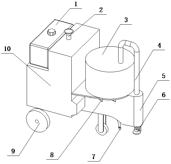
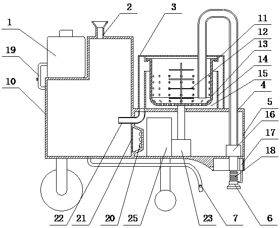
[0021] The automatic machine tool cutting fluid recovery processing machine of the present invention is realized in this way: the automatic machine tool cutting fluid recovery processing machine of the present invention is composed of a separation device and a sterilizing device, and the separation device is composed of a centrifugal sedimentation box (3), a connecting pipe (4), and a driving box ( 5), suction pipe (6), reinforcement rib (8), limit ring (11), stirring blade (12), centrifugal cylinder (13), partition (14), sedimentation chamber (15), liquid suction pump (16), electric telescopic rod (17), corrugated telescopic tube (18), driving motor (23) and buckle groove (24), the centrifugal sedimentation box (3) is placed on the driving box (5), and the centrifugal A reinforcing rib (8) is placed between the settling box (3) and the driving box (5), the liquid suction pump (16) is placed in the driving box (5), and one end of the liquid outlet pipe (22) and the liquid sucti...

Embodiment 2

[0026] The difference between this embodiment and Embodiment 1 is: the sterilization box (10) has a plurality of stirring rollers (26) built in; when in use, the plurality of stirring rollers (26) stir the cutting fluid to improve the mixing adjustment of the cutting fluid speed;

[0027] The design of reinforcing ribs (8) placed between the centrifugal sedimentation box (3) and the driving box (5) makes the overall structure of the device stable;

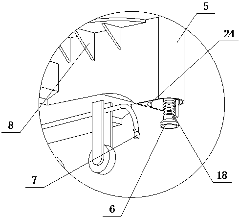
[0028] The diameter of the lower section of the suction pipe (6) is designed to be larger than the diameter of its upper end, so that the contact area between the suction pipe (6) and the cutting fluid is large, and the suction effect on the cutting fluid is good;

[0029] The connection between the upper section and the lower section of the suction pipe (6) is designed as a slope, which makes the suction and delivery of the cutting fluid by the suction pipe (6) smooth and reduces resistance;

[0030] The design of the gasket betw...


PUM


Abstract

The invention discloses an automatic machine tool cutting fluid recovery processor, which can perform solid-liquid separation on a cutting fluid, treat a deteriorated cutting fluid and simplify a process, and is convenient to use. The automatic machine tool cutting fluid recovery processor is characterized in that a centrifugal precipitation box is arranged on a driving box; a reinforcing rib is arranged between the centrifugal precipitation box and the driving box; a liquid sucking pump is arranged in the driving box; one end of a liquid outlet pipe is connected with the liquid outlet end ofthe liquid sucking pump; the other end of the liquid outlet pipe upwards penetrates out of the driving box, penetrates through the top of the centrifugal precipitation box and is arranged in the centrifugal precipitation box; one end of a corrugated telescopic pipe is connected with the liquid inlet end of the liquid sucking pump; the liquid sucking pipe is connected with the other end of the corrugated telescopic pipe; the liquid sucking pipe is divided into an upper section and a lower section, the diameter of the lower section of the liquid sucking pipe is larger than that of the upper endof the liquid sucking pipe, and a slope is arranged at the joint of the upper section and the lower section of the liquid sucking pipe; and one end of an electric telescopic rod is fixed at the bottomof the driving box.

Description

technical field [0001] The invention discloses an automatic machine tool cutting fluid recovery processing machine, which relates to a processing machine for recycling and processing the automatic machine tool cutting fluid, and belongs to the field of automation equipment. In particular, it relates to a processing machine capable of solid-liquid separation of cutting fluid and processing of metamorphic cutting fluid, which simplifies the process and is convenient to use. Background technique [0002] Cutting fluid is an industrial liquid used in metal cutting and grinding to cool and lubricate cutting tools and workpieces. Cooling performance, lubricating performance, anti-rust performance, degreasing and cleaning function, anti-corrosion function, easy to dilute, etc. After a period of use, the cutting fluid will be mixed with waste and impurities during processing, and at the same time due to The irregular operating habits of the workshop workers and their long-term non-...

Claims


Application Information

Patent Timeline
Patent Type & Authority Applications(China)
IPC IPC(8): C10M175/00
CPCC10M175/00
Inventor 不公告发明人
Owner XUZHOU OUBAI RUI INTELLIGENT EQUIP CO LTD
Why Eureka
Try Eureka