Supporting structure and plugging sleeve structure for anchor rod gap grouting

A technology for supporting structures and bolts, which is applied in infrastructure engineering, excavation, construction, etc., can solve the problems of quality and safety hazards, bolt leakage, endangering engineering construction safety, etc. Reliability, grouting material saving effect

Inactive Publication Date: 2020-06-19
POWERCHINA HUADONG ENG COPORATION LTD
View PDF4 Cites 0 Cited by
  • Summary
  • Abstract
  • Description
  • Claims
  • Application Information

AI Technical Summary

Problems solved by technology

[0002] Hydropower projects or other engineering constructions are carried out in the alpine valley basin, the valley is deeply cut, the joints and fissures are developed on both sides of the slope, the unloading effect of the rock mass is obvious, the rock mass is partially loose, and the local blocks with prominent ridges or steep slopes form dangerous rock masses or Dangerous stone groups, poor stability, directly endanger the safety of engineering construction, need to take corresponding removal or reinforcement measures
[0003] During the anchoring and reinforcement treatment of the dangerous rock mass, it was found that due to the obvious unloading effect, there were unforeseen large unloading cracks inside the rock mass, and the grout leakage was serious during the bolt grouting process, and due to the large range of cracks, filling If the grouting compactness of the anchor bolt cannot be guaranteed, it will directly affect the effect of the anchor bolt reinforcement treatment, and there will be corresponding quality and safety hazards at the same time.

Method used


Image

  • Supporting structure and plugging sleeve structure for anchor rod gap grouting
  • Supporting structure and plugging sleeve structure for anchor rod gap grouting
  • Supporting structure and plugging sleeve structure for anchor rod gap grouting

Examples


Embodiment Construction

[0016] Embodiments of the present invention are:

[0017] During the bolt drilling construction process, abnormal situations such as drill drop and non-return wind occurred, and the drilling records were made in time. After the drilling was completed, the drilling camera equipment was used to detect large internal cracks, and a detailed map of the crack location was drawn. Then the plugging structure of the present invention is installed at the position corresponding to the occurrence of cracks in the anchor rod. Or, if there is a huge amount of grout and no grout return during grouting, the bolt should be withdrawn in time and the plugging structure of the present invention should be adopted.

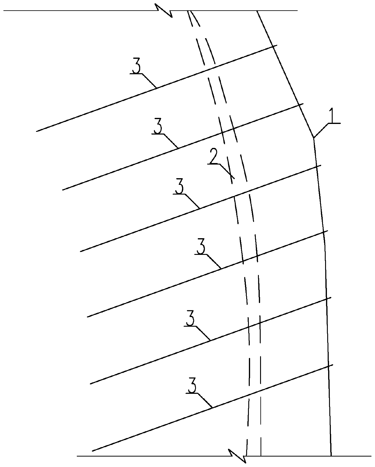
[0018] like figure 1 As shown, reinforcement treatment is required for the dangerous rock mass 1. However, during the grouting process of the support bolt 3, a large amount of grout was consumed and there was no grout return. A fissure 2 with a width of about 0.3m was found at about ...


PUM


Abstract

The invention provides a supporting structure and a plugging sleeve structure for anchor rod gap grouting. The supporting structure comprises an anchor rod; a sleeve is arranged at the position, corresponding to a rock mass crack, of the anchor rod, and the length of the sleeve is greater than the width of the rock mass crack; and water-swellable waterstop strips are arranged at two ends or withinthe full-length range of the sleeve, and a gap between the sleeve and the anchor rod allows a grouting pipe to pass through. According to the supporting structure and the plugging sleeve structure, plugging can be carried out according to the accurate position of the crack, the problem of untight grouting is avoided, the reinforcement quality is ensured, and a large number of grouting materials can be saved. Meanwhile, the plugging sleeve structure at the crack can play a role as an anti-corrosion layer, and the safety and reliability of long-term operation are ensured.

Description

technical field [0001] The invention relates to a support structure and a plugging sleeve structure for bolt grouting through joints thereof, and is mainly suitable for grouting and grouting treatment of dangerous rock masses on rock slopes with developed unloading and developed rock slopes. Background technique [0002] Hydropower projects or other engineering constructions are carried out in the alpine valley basin, the valley is deeply cut, the joints and fissures are developed on both sides of the slope, the unloading effect of the rock mass is obvious, the rock mass is partially loose, and the local blocks with prominent ridges or steep slopes form dangerous rock masses or Dangerous stone groups have poor stability and directly endanger the construction safety of the project, and corresponding removal or reinforcement measures are required. [0003] During the anchoring and reinforcement treatment of the dangerous rock mass, it was found that due to the obvious unloadin...

Claims


Application Information

Patent Timeline
Patent Type & Authority Applications(China)
IPC IPC(8): E02D17/20
CPCE02D17/20
Inventor 张叶林张洋陈国良
Owner POWERCHINA HUADONG ENG COPORATION LTD
Why Eureka
Try Eureka