Plastering method and device

A plastering surface and corresponding position technology, which is applied in the direction of architecture and building structure, can solve the problems of plastering surface inclination, height difference, unevenness, and achieve the effect of ensuring flatness

Active Publication Date: 2020-06-19
GUANGDONG BOZHILIN ROBOT CO LTD
View PDF4 Cites 0 Cited by
  • Summary
  • Abstract
  • Description
  • Claims
  • Application Information

AI Technical Summary

Problems solved by technology

[0003] The purpose of the embodiments of the present application is to provide a pre-plastering method and device, set a reference reference for the movement of the plastering panel, ensure that the plastering panel moves at a fixed

Method used


Image

  • Plastering method and device
  • Plastering method and device
  • Plastering method and device

Examples


Embodiment 2

[0059] The embodiment of the present application also provides a plastering method, such as Figure 4 Shown is the flow chart of the plastering method. Applied to the plastering device described in embodiment 1, the method may specifically include the following steps:

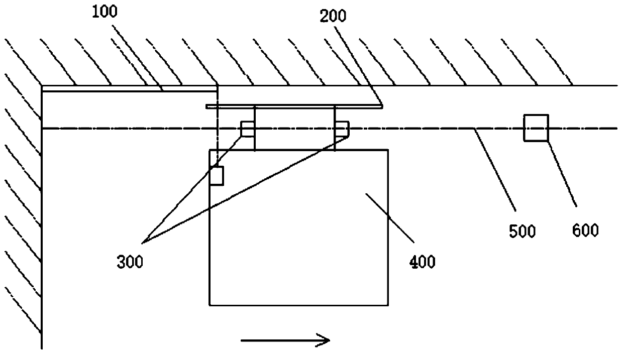
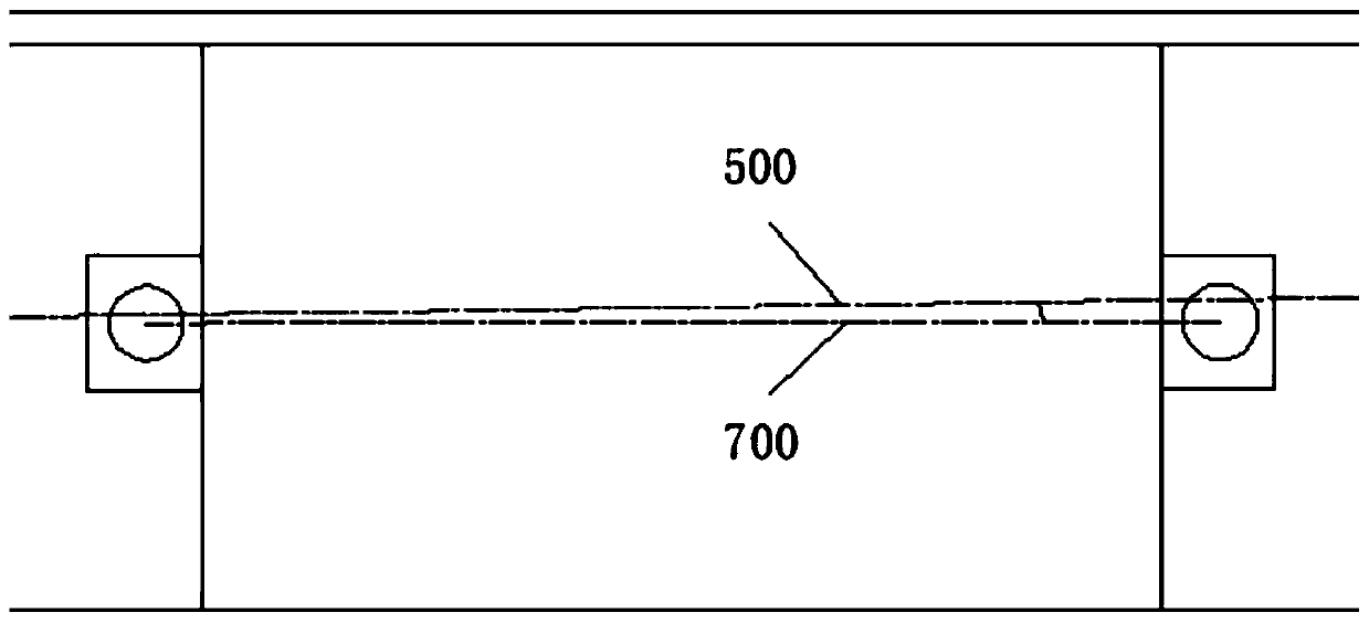
[0060] S100: Use the laser line projector 600 to emit laser lines 500 to the vertical wall surface of the plastered wall and form the laser line 500 into a laser beam surface, the laser beam surface is set at a fixed distance from the plastered wall surface, as A reference datum for the movement of the plastered panel 200;

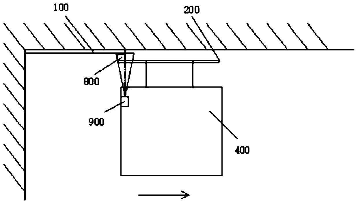
[0061] S200: Use the plastering panel 200 to move and plaster the plastered wall surface according to the reference standard.

[0062] In the above implementation process, the laser line 500 emitted by the laser line projector 600 constitutes the laser line beam surface. Since the laser line beam surface is parallel to the plastered wall and the distance is fixed, the laser line beam surf...

Embodiment 3

[0073] The embodiment of the present application also provides an electronic device, the electronic device includes a memory and a processor, the memory is used to store a computer program, and the processor runs the computer program so that the computer device executes the method described in Embodiment 1. The plastering method described in any one.

[0074] The embodiment of the present application also provides a readable storage medium, where computer program instructions are stored in the readable storage medium, and when the computer program instructions are read and executed by a processor, any one of the steps described in Embodiment 1 is executed. The plastering method described above.


PUM


Abstract

Embodiments of the application provide a plastering method and device, and relate to the technical field of plastering. The device comprises a laser demarcation device, a plastering panel and at leasttwo image sensors, wherein the laser demarcation device is installed on a parallel plane set at a fixed distance from a to-be-plastered wall surface, and is used for emitting laser rays parallel withthe to-be-plastered wall surface so as to form a laser ray beam surface and the laser ray beam surface serves as a reference datum for movement of the plastering panel; the plastering panel is used for performing mobile plastering on the to-be-plastered wall surface according to the reference datum; and the at least two image sensors are installed on a plane parallel with the plastering panel, and is used for photographing the laser rays, and acquiring deflection included angles between a straight line where the at least two image sensors are located and the laser rays through image data of the laser rays so as to adjust a horizontal angle of the plastering panel and/or the distance from the plastering panel to the laser ray beam surface. The problems that height difference is present between all plastered surfaces and the plastered surfaces incline and uneven due to a moving way of an existing plastering panel are solved.

Description

technical field [0001] The present application relates to the technical field of plastering, and in particular, to a plastering method and device. Background technique [0002] During the working process of the existing plastering machine, due to the limitation of the size of the plastering panel, it is necessary to move plastering one by one. However, the plastering machine needs to be moved under the driving of the navigation and the steering wheel or manually pushed. These two moving methods will lead to problems of height difference between the plastering surfaces and the inclination and unevenness of the plastering surfaces. Contents of the invention [0003] The purpose of the embodiments of the present application is to provide a pre-plastering method and device, set a reference reference for the movement of the plastering panel, ensure that the plastering panel moves at a fixed distance from the wall, and solve the existing problem of plastering panel movement The...

Claims


Application Information

Patent Timeline
IPC IPC(8): E04F21/08E04F21/04E04F21/16
CPCE04F21/04E04F21/08E04F21/161
Inventor 李健米野
Owner GUANGDONG BOZHILIN ROBOT CO LTD
Why Eureka
Try Eureka