
Real-time online monitoring system for vibration of communication optical cable

A monitoring system, optical fiber vibration technology, applied in the direction of measuring devices, measuring ultrasonic/sonic/infrasonic waves, instruments, etc., can solve the problem that the optical cable monitoring is not comprehensive enough, the staff cannot make timely, and the staff cannot understand the sensor in detail Monitor the situation and other issues to achieve the effect of accurate detection results

Active Publication Date: 2020-06-19
SHENZHEN SDG INFORMATION CO LTD
View PDF12 Cites 4 Cited by
  • Summary
  • Abstract
  • Description
  • Claims
  • Application Information

AI Technical Summary

Problems solved by technology

[0004] Aiming at the deficiencies of the prior art, the present invention provides a real-time on-line monitoring system for communication optical cable vibration, which solves the problem that the monitoring of the optical cable is not comprehensive enough and the staff cannot understand the sensor vibration in detail. The monitoring situation, so that when the cable fails, the staff cannot take corresponding measures in time

Method used


Image

  • Real-time online monitoring system for vibration of communication optical cable
  • Real-time online monitoring system for vibration of communication optical cable
  • Real-time online monitoring system for vibration of communication optical cable

Examples


Embodiment Construction

[0027] The following will clearly and completely describe the technical solutions in the embodiments of the present invention with reference to the accompanying drawings in the embodiments of the present invention. Obviously, the described embodiments are only some, not all, embodiments of the present invention. Based on the embodiments of the present invention, all other embodiments obtained by persons of ordinary skill in the art without making creative efforts belong to the protection scope of the present invention.

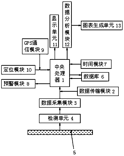
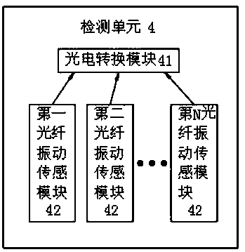
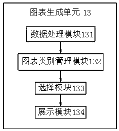
[0028] see Figure 1-7 , the present invention provides a technical solution: a communication optical cable vibration real-time online monitoring system, including a central processing unit 1, the central processing unit 1 and the data acquisition module 3 are connected through a data transmission module 2, and the data acquisition module 3 The input end of the detection unit 4 is electrically connected to the output end of the detection unit 4 through a wire,...


PUM


Abstract

The invention discloses a real-time online monitoring system for vibration of a communication optical cable. The system comprises a central processing unit, the central processing unit is in transmission connection with a data collection module through a data transmission module, the input end of the data collection module is electrically connected with the output end of a detection unit through awire, and the input end of the detection unit is electrically connected with the output end of a cable through a wire. The invention relates to the technical field of optical cable vibration sensingmonitoring. The invention discloses a real-time online monitoring system for vibration of a communication optical cable. The output end of a selection module is electrically connected with the input end of a display module through a wire; vibration detection can be performed on multiple positions on the cable so that the detection result is enabled to be more accurate and more comprehensive, corresponding chart information can be selected according to the type of the vibration information, the chart information can be enabled to be displayed to the staff in the form of a chart, and the staff is enabled to more visually understand the situation of the detected information data.

Description

technical field [0001] The invention relates to the technical field of optical cable vibration sensing and monitoring, in particular to a real-time on-line monitoring system for communication optical cable vibration. Background technique [0002] Optical cables are manufactured to meet optical, mechanical or environmental performance specifications. It is a communication cable assembly that uses one or more optical fibers placed in a sheath as a transmission medium and can be used individually or in groups. Optical cables It is mainly composed of optical fiber (glass filament as thin as hair), plastic protective sleeve and plastic sheath. The optical cable is mainly used in the construction of communication engineering, and the vibration of the optical cable is that the laser emits DC monochromatic light waves. Direct and reverse coupling into the two-core sensing optical fiber to form a forward and reverse loop Mach-Zehnder interference optical signal. During the use of the...

Claims


Application Information

Patent Timeline
Patent Type & Authority Applications(China)
IPC IPC(8): G01H9/00
CPCG01H9/004
Inventor 陈晓波邓伟锋赵丽娜李耀均
Owner SHENZHEN SDG INFORMATION CO LTD
Learn More