
Fiber grating pressure sensor and using method thereof

A pressure sensor and fiber grating technology, applied in the field of data sensors, can solve the problems of insufficient pressure sensitivity and temperature compensation, and achieve the effects of enhanced sensitivity, small resilience and good stability

Active Publication Date: 2020-06-19
UNIV OF ELECTRONICS SCI & TECH OF CHINA
View PDF15 Cites 3 Cited by
  • Summary
  • Abstract
  • Description
  • Claims
  • Application Information

AI Technical Summary

Problems solved by technology

Its shortcomings are: it cannot solve the problem of temperature compensation well, the sensitivity to pressure is not high enough, and the measurement of liquid level is affected by the liquid density and the acceleration of gravity

Method used


Image

  • Fiber grating pressure sensor and using method thereof
  • Fiber grating pressure sensor and using method thereof
  • Fiber grating pressure sensor and using method thereof

Examples


Embodiment Construction

[0037] The specific embodiments of the present invention are described below so that those skilled in the art can understand the present invention, but it should be clear that the present invention is not limited to the scope of the specific embodiments. For those of ordinary skill in the art, as long as various changes Within the spirit and scope of the present invention defined and determined by the appended claims, these changes are obvious, and all inventions and creations using the concept of the present invention are included in the protection list.

[0038] Embodiments of the present invention will be described in detail below in conjunction with the accompanying drawings.

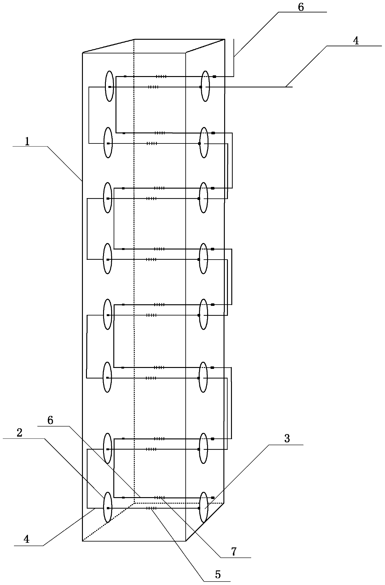
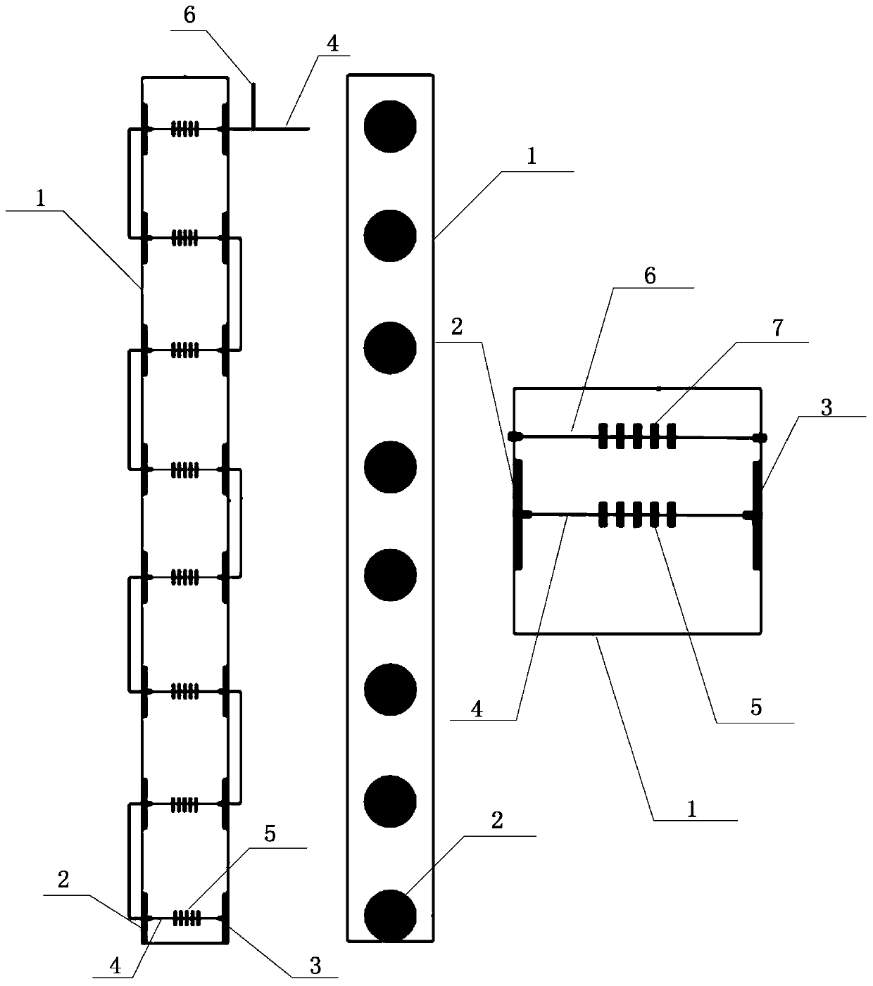
[0039] Such as figure 1 and figure 2 Commonly shown, a fiber grating pressure sensor includes a housing 1 and a pressure optical fiber 4. The housing 1 is a cuboid with a cavity, and the center line of one side is provided with N first round holes at equal intervals. Each of the first round holes ...


PUM


Abstract

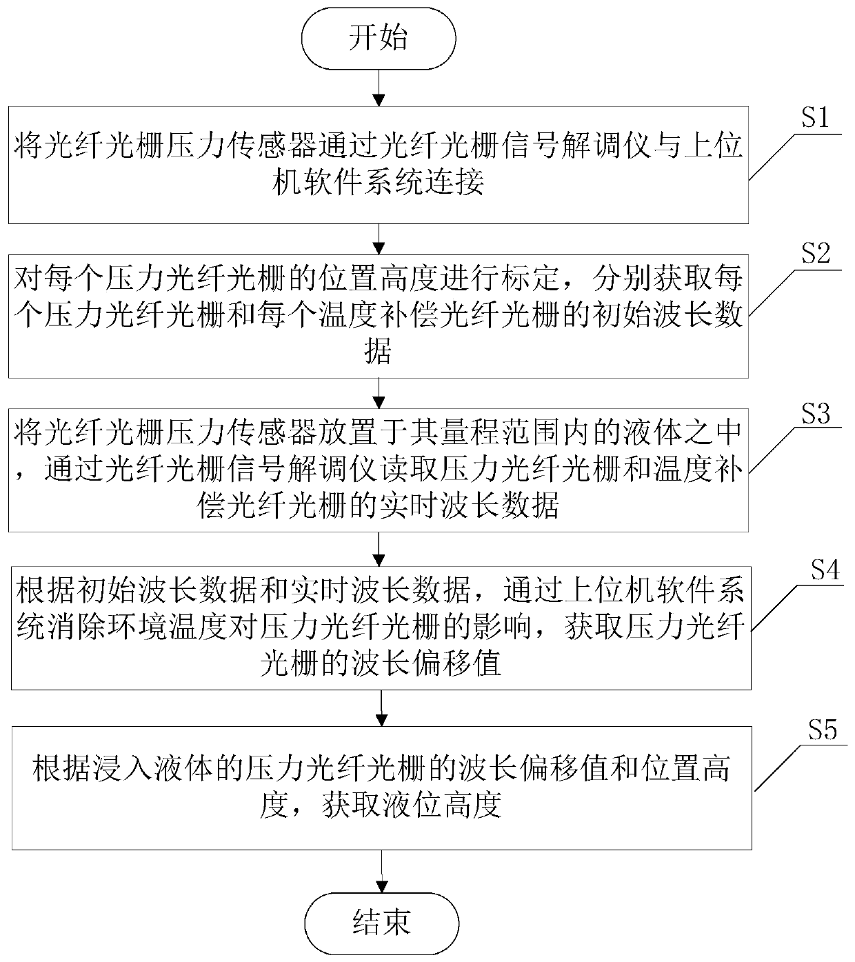
The invention discloses a fiber grating pressure sensor. A using method of the fiber grating pressure sensor comprises the steps that the fiber grating pressure sensor is connected with an upper computer software system through a fiber grating signal demodulator; the position height of each pressure fiber grating is calibrated, and initial wavelength data of each pressure fiber grating and each temperature compensation fiber grating are obtained; the fiber grating pressure sensor is placed in liquid within the measuring range of the fiber grating pressure sensor, and real-time wavelength dataof the pressure fiber gratings and the temperature compensation fiber gratings are read through the fiber grating signal demodulator; according to the initial wavelength data and the real-time wavelength data, the influence of the environment temperature on the pressure fiber gratings is eliminated, and wavelength deviation values of the pressure fiber gratings are obtained; and the liquid level height is obtained according to the wavelength deviation values and the position heights of all the pressure fiber gratings. The liquid level height measured by the fiber grating pressure sensor is accurate and is not influenced by liquid density and gravitational acceleration.

Description

technical field [0001] The invention relates to the field of data sensors, and specifically relates to a fiber grating pressure sensor and a method for using the same. Background technique [0002] Due to its strong anti-electromagnetic interference ability and high measurement accuracy and linearity for pressure measurement parameters, fiber grating sensors are gradually being used in liquid level monitoring in special environments. The FBG pressure sensor is based on the linear relationship between hydraulic pressure and FBG Bragg wavelength shift response. In the prior art, a metal diaphragm type optical fiber grating pressure sensor is proposed. Its working principle is that the liquid level pressure has a linear relationship with the reflection wavelength of the optical fiber grating, and its linearity reaches 0.9999. The deformation of the isolation diaphragm is caused by the change of liquid pressure, from The fiber grating is not deformed accordingly, and the change...

Claims


Application Information

Patent Timeline
Patent Type & Authority Applications(China)
IPC IPC(8): G01L11/02G01L19/04G01K11/32G01F23/14G01K11/3206
CPCG01L11/025G01L19/04G01K11/32G01F23/14
Inventor 唐杰吴宇王琳
Owner UNIV OF ELECTRONICS SCI & TECH OF CHINA
Learn More