Parallel-shaft output reducer bending rigidity testing system

A bending stiffness and testing system technology, applied in the field of mechanical transmission, can solve the problems of cumbersome operation of adding discrete loads, cumbersome recording and numerical processing, error in test results, etc., and achieves the effect of easy-to-obtain structure, simple structure and reduced production cost.

Active Publication Date: 2020-06-19
CHONGQING UNIV
View PDF11 Cites 1 Cited by
  • Summary
  • Abstract
  • Description
  • Claims
  • Application Information

AI Technical Summary

Problems solved by technology

At present, the performance test of the bending stiffness of the reducer usually adopts a bench test. The output shaft is loaded through the counterweight, and the dial gauge reads the deflection of the output shaft under the load, and then obtains the bending stiffness value of the reducer. This test The addition of the method load is discrete, and the deflection angle of the output shaft under several loads is recorded, and then the fitting curve of the bending stiffness of the reducer is drawn. The test results have large errors. In addition, the discrete load addition operation is cumbersome, time-consuming and laborious. Low efficiency; the recording of test results and numerical processing are also relatively cumbersome

Method used


Image

  • Parallel-shaft output reducer bending rigidity testing system
  • Parallel-shaft output reducer bending rigidity testing system

Examples


Embodiment Construction

[0032] In order to make the objectives, technical solutions, and advantages of the embodiments of the present invention clearer, the technical solutions in the embodiments of the present invention will be described clearly and completely in conjunction with the accompanying drawings in the embodiments of the present invention. Obviously, the described embodiments It is a part of the embodiments of the present invention, not all the embodiments. The components of the embodiments of the present invention generally described and illustrated in the drawings herein may be arranged and designed in various different configurations.

[0033] Therefore, the following detailed description of the embodiments of the present invention provided in the accompanying drawings is not intended to limit the scope of the claimed invention, but merely represents selected embodiments of the present invention. Based on the embodiments of the present invention, all other embodiments obtained by those of ...


PUM


Abstract

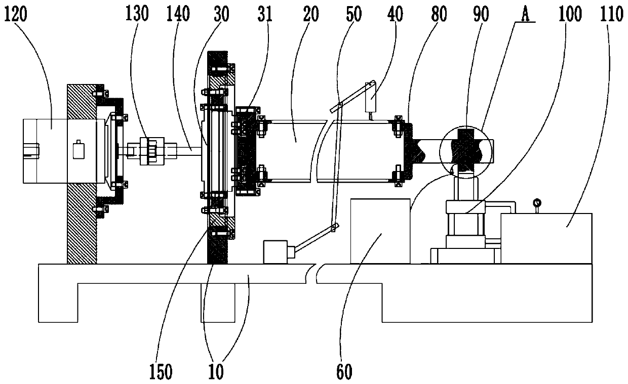
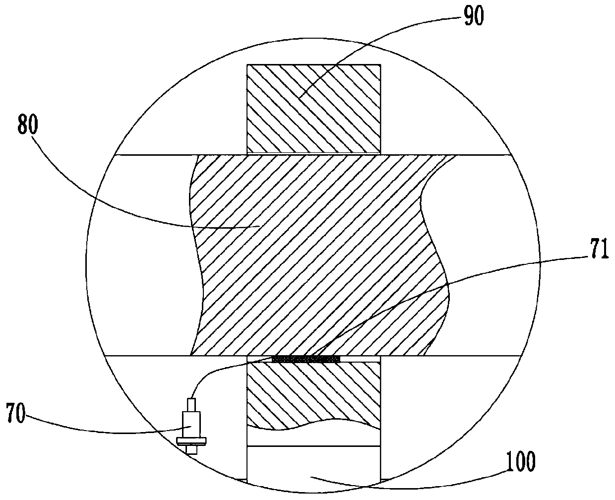
The invention provides a parallel-shaft output reducer bending rigidity testing system, and relates to the technical field of mechanical transmission. The parallel-shaft output reducer bending rigidity testing system comprises a test board, a test piece, a loading system, a pressure sensor and a displacement detection assembly. The test board is used for fixedly installing the reducer. The test piece can be fixed with the output end of the reducer. At the moment, the loading system can push the test piece to enable the test piece and the output end of the reducer to slightly swing. The pressure sensor is used for detecting the pressure between the test piece and the loading system, and the pressure at the moment is the radial force applied to swing of the test piece by the loading system.The displacement detection assembly is used for detecting the displacement variation of the preset position of the test piece when the test piece swings.

Description

Technical field [0001] The invention relates to the technical field of mechanical transmission, in particular to a testing system for the bending stiffness of a parallel shaft output reducer. Background technique [0002] The bending stiffness is an important indicator of the performance of the parallel shaft output reducer, and it has an important influence on the stiffness of the entire mechanical equipment or transmission system. At present, the performance test of the bending stiffness of the reducer usually adopts a bench test. The output shaft is loaded by a counterweight, and the dial indicator reads the deflection of the output shaft under the load, and then obtains the bending stiffness value of the reducer. The method load is added discretely, and the deflection angle of the output shaft under several loads is recorded, and then the fitting curve of the bending stiffness of the reducer is drawn. The test results have large errors. In addition, the discrete load adding o...

Claims


Application Information

Patent Timeline
IPC IPC(8): G01M13/02G01M5/00
CPCG01M13/02G01M5/0075
Inventor 李朝阳吴虹屿黄建杜兴罗羽杨陈兵奎
Owner CHONGQING UNIV
Why Eureka
Try Eureka