High-voltage direct-current transmission line fault distance measurement method

A transmission line, high-voltage direct current technology, applied in the direction of fault location, fault detection according to conductor type, and electrical measurement, can solve the problem of low measurement accuracy and achieve high accuracy, short data time window, excellent accuracy and The effect of stability

Active Publication Date: 2020-06-19
YUNNAN POWER GRID +1
View PDF6 Cites 5 Cited by
  • Summary
  • Abstract
  • Description
  • Claims
  • Application Information

AI Technical Summary

Problems solved by technology

[0004] The present invention provides a high-voltage direct current transmission line fault location method, which is used to solve the problem of low measurement accuracy in fault location in a complex environment caused by the existing fault location method only considering the rectification side current

Method used


Image

  • High-voltage direct-current transmission line fault distance measurement method
  • High-voltage direct-current transmission line fault distance measurement method
  • High-voltage direct-current transmission line fault distance measurement method

Examples


Embodiment 1

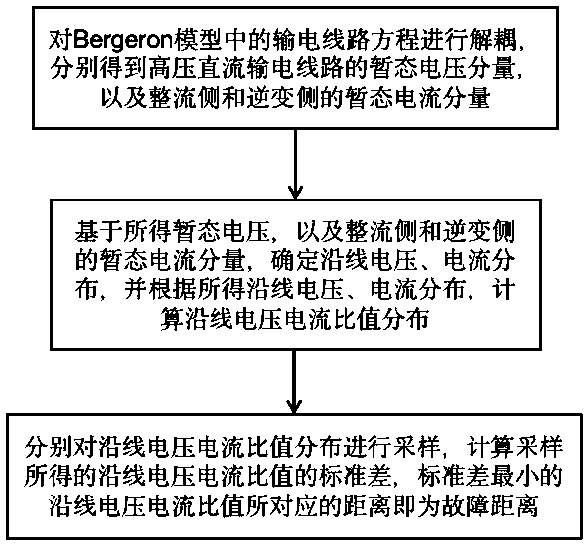
[0037] A high voltage direct current transmission line fault location method, such asfigure 1 shown, including the following steps:

[0038] S1. Decoupling the transmission line equation in the Bergeron model to obtain the transient voltage component of the HVDC transmission line and the transient current component of the rectifier side and the inverter side;

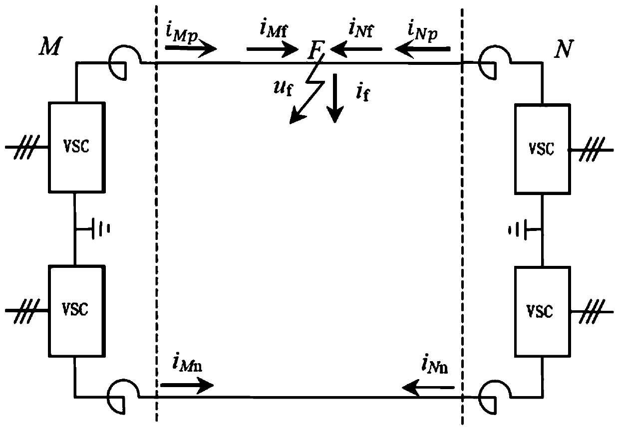
[0039] Specifically, such as figure 2 Shown is a schematic diagram of a single-pole fault of a bipolar DC transmission line, where, i Mp and i Mn are the positive and negative currents measured on the rectifier side (M side), respectively; i Np and i Nn are the positive and negative currents measured on the inverter side (N side), respectively; i Mf is the current injected into the fault point from terminal M; i Nf is the current injected into the fault point from the N terminal; the i Mf and i Nf Denoted as boost current. If a fault occurs at F at a certain moment, according to Kirchhoff's law, there are:

[...

Embodiment 2

[0077] A storage medium, when the computer reads the instructions, the computer is made to execute the fault location method for high-voltage direct current transmission lines provided in Embodiment 1 of the present invention.


PUM


Abstract

The invention discloses a high-voltage direct-current power transmission line fault distance measurement method. The method comprises the following steps: S1, decoupling a power transmission line equation in a Bergeron model, and respectively obtaining a transient voltage component of a high-voltage direct-current power transmission line and transient current components of a rectification side andan inversion side; S2, determining voltage and current distribution along the line based on the obtained transient voltage and the transient current components of the rectification side and the inversion side, and calculating voltage and current ratio distribution along the line according to the obtained voltage and current distribution along the line; and S3, sampling the voltage-current ratio distribution along the line, calculating the standard deviation of the voltage-current ratio along the line obtained by sampling, and taking the distance corresponding to the voltage-current ratio along the line with the minimum standard deviation as a fault distance. According to the method, a filtering algorithm does not need to be involved, the inversion side auxiliary increasing current is introduced when the fault current is determined, the required data time window is short, and when fault distance measurement is carried out in a complex environment, the accuracy of fault distance measurement is high; and the method has better stable distance measurement performance.

Description

technical field [0001] The invention belongs to the field of electric fault diagnosis, and more specifically relates to a method for fault distance measurement of a high-voltage direct current transmission line. Background technique [0002] my country has a vast territory, and the distribution of energy and load is reversed. The electric energy from the energy center in the west needs to be transported to the load center in the east over long distances. In order to meet the demand for large-capacity power transmission, my country has vigorously developed DC transmission technology and successively built major UHV DC transmission projects, including Ximeng-Jiangsu Taizhou ±800 kV UHV DC Project, Gansu Jiuquan-Hunan ±800 kV UHV DC Project , Northwest Yunnan-Guangdong ±800 kV UHV DC project, etc. The characteristic of direct current transmission is that it can realize long-distance "point-to-point" power transmission, which is its advantage and its disadvantage. The disadvant...

Claims


Application Information

Patent Timeline
Patent Type & Authority Applications(China)
IPC IPC(8): G01R31/08
CPCG01R31/085G01R31/088Y04S10/52
Inventor 李本瑜任俊谕刘源赵明石恒初游昊杨远航张琳波陈金富
Owner YUNNAN POWER GRID
Why Eureka
Try Eureka