Power-on control circuit and electronic equipment with same

A technology of electrical control and electrical control signal, which is applied in the direction of electrical components, output power conversion devices, etc., can solve problems such as the inability to meet the needs of fast power-on, and achieve the effect of fast power-on and meeting the power-on demand

Inactive Publication Date: 2020-06-19
BEIJING BITMAIN TECH LTD
View PDF8 Cites 1 Cited by
  • Summary
  • Abstract
  • Description
  • Claims
  • Application Information

AI Technical Summary

Problems solved by technology

However, in the application of some ASIC integrated chips, contrary to the application requirements of conventional circuits, it requires the power supply to be powered on quickly so that it can quickly enter a stable working state. Therefore, the slow power-on method cannot meet the requirements of fast power-on. need

Method used


Image

  • Power-on control circuit and electronic equipment with same
  • Power-on control circuit and electronic equipment with same
  • Power-on control circuit and electronic equipment with same

Examples


Embodiment Construction

[0026] Embodiments of the present invention are described in detail below, and the embodiments described with reference to the drawings are exemplary, and embodiments of the present invention are described in detail below.

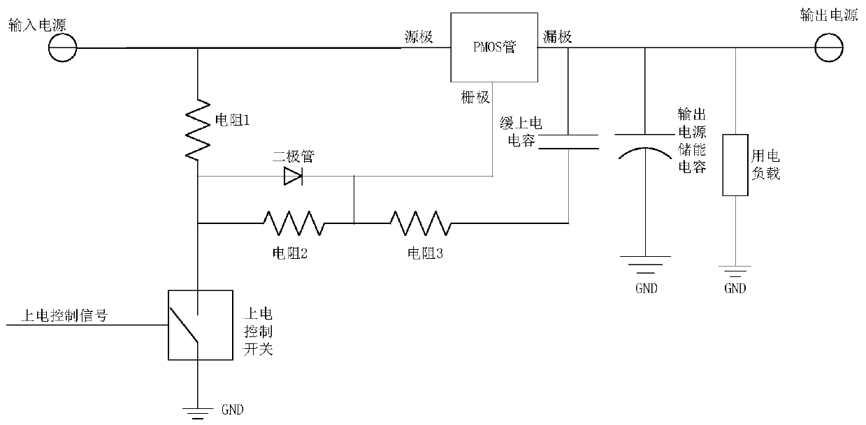
[0027] For such as figure 1 The specific working process of the slow power-on control circuit shown is as follows:

[0028] Specifically, the default power-on control switch is off. If the external power supply is powered on, the slow power-on capacitor will be fully charged quickly through resistor 1, diode, and resistor 3. As a result, the voltage difference between the gate and the source of the PMOS transistor does not meet the threshold turn-on voltage of the PMOS transistor, and the PMOS transistor is in a disconnected state, so that the power-consuming load end is in a power-off state.

[0029] When the switch control signal is received to control the power-on control switch from the off state to the closed state, the slow-on capacitor will slowly ...


PUM


Abstract

The invention provides a power-on control circuit and electronic equipment with the same. The power-on control circuit comprises: an input energy storage module, wherein a first end of the input energy storage module is connected with an input power supply, and a second end of the input energy storage module is connected with a grounding end; a switch module, wherein the first end of the switch module is respectively connected with the input power supply and the first end of the input energy storage module, the second end of the switch module is connected with the power supply end of an electric load, and the switch module is used for being switched on when a power-on control signal is detected, so that the input power supply and the input energy storage module supply power to the electricload; and a control module, wherein the control module is used for outputting the power-on control signal when a power-on instruction is detected. According to the power-on control circuit disclosedby the invention, when the switch module is in a conduction state, instantaneous large current required by a load is rapidly provided through the input power supply and the input energy storage module, and rapid power-on of the load can be realized.

Description

technical field [0001] The present invention relates to the technical field of electronic equipment, in particular to a power-on control circuit and electronic equipment. Background technique [0002] In circuit design, for some circuits such as ASIC circuit applications, such as figure 1 As shown, the slow power-on method is often used, that is, to slow down the power-on speed of its power supply, and PMOS tubes are generally used to achieve slow power-on. However, in the application of some ASIC integrated chips, contrary to the application requirements of conventional circuits, it requires the power supply to be powered on quickly so that it can quickly enter a stable working state. Therefore, the slow power-on method cannot meet the requirements of fast power-on. need. Contents of the invention [0003] The present invention aims to solve at least one of the technical problems existing in the prior art. Therefore, the first object of the present invention is to prov...

Claims


Application Information

Patent Timeline
Patent Type & Authority Applications(China)
IPC IPC(8): H02M1/36
CPCH02M1/36
Inventor 周雪松
Owner BEIJING BITMAIN TECH LTD
Why Eureka
Try Eureka