Signal transmission method and device and electronic equipment
A signal transmission and signal technology, applied in transmission systems, radio transmission systems, electrical components, etc., can solve the problem of low effective signal performance
- Summary
- Abstract
- Description
- Claims
- Application Information
AI Technical Summary
Problems solved by technology
Method used
Image

Examples
Embodiment Construction
[0094] The following will clearly and completely describe the technical solutions in the embodiments of the present invention with reference to the accompanying drawings in the embodiments of the present invention. Obviously, the described embodiments are only some, not all, embodiments of the present invention. Based on the embodiments of the present invention, all other embodiments obtained by persons of ordinary skill in the art without making creative efforts belong to the protection scope of the present invention.
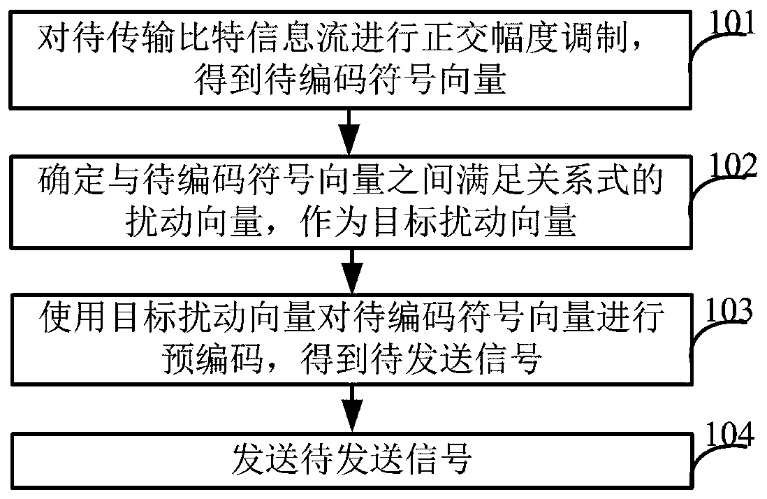
[0095] The embodiment of the present invention discloses a signal transmission method, which is applied to the sending end equipment, such as figure 1 As shown, the following steps may be included:
[0096] Step 101, performing quadrature amplitude modulation on the bit information stream to be transmitted to obtain a symbol vector to be encoded.
[0097] Step 102, based on the pre-established relationship between the symbol vector and the disturbance vector,...
PUM
 Abstract
Description
Claims
Application Information