Degumming device and method of cut silicon rod

A degumming device, silicon rod technology, applied in fine working devices, chemical instruments and methods, cleaning methods using tools, etc., can solve problems such as affecting the process, low labor efficiency, residual stress on the edge of silicon wafers, etc., to avoid extrusion The effect of crushing fragments, improving cleanliness and avoiding slippage

Active Publication Date: 2020-06-23
XUZHOU XINJING SEMICON TECH CO LTD +1
View PDF9 Cites 4 Cited by
  • Summary
  • Abstract
  • Description
  • Claims
  • Application Information

AI Technical Summary

Problems solved by technology

In the existing degumming method, on the one hand, silicon powder or cutting mortar is likely to remain on the surface of the silicon wafer after degumming, which affects the progress of the subsequent process; The surface tension between the wafer and the silicon wafer is too strong, and it is easy to cause residual stress on the edge of the silicon wafer during the process of taking and dividing the wafer, resulting in chip (edge ​​chipping), and the labor efficiency is low, resulting in low yield and high cost.
[0003] Therefore, the existing degumming technology of silicon rod after cutting needs to be improved

Method used


Image

  • Degumming device and method of cut silicon rod
  • Degumming device and method of cut silicon rod
  • Degumming device and method of cut silicon rod

Examples


Embodiment Construction

[0054] Embodiments of the present invention are described in detail below, examples of which are shown in the drawings, wherein the same or similar reference numerals designate the same or similar elements or elements having the same or similar functions throughout. The embodiments described below by referring to the figures are exemplary and are intended to explain the present invention and should not be construed as limiting the present invention.

[0055] In describing the present invention, it is to be understood that the terms "center", "longitudinal", "transverse", "length", "width", "thickness", "upper", "lower", "front", " Back", "Left", "Right", "Vertical", "Horizontal", "Top", "Bottom", "Inner", "Outer", "Clockwise", "Counterclockwise", "Axial" , "radial", "circumferential" and other indicated orientations or positional relationships are based on the orientations or positional relationships shown in the drawings, and are only for the convenience of describing the pre...


PUM


Abstract

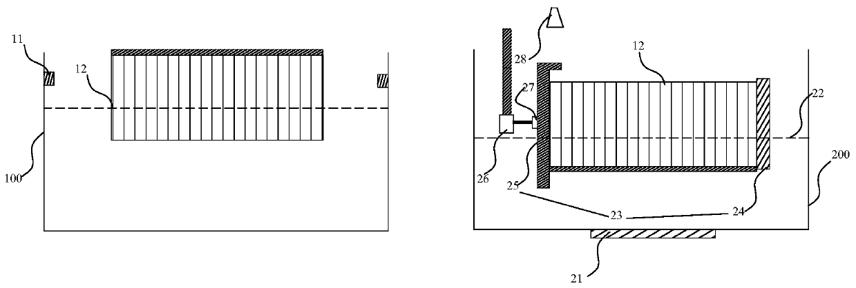
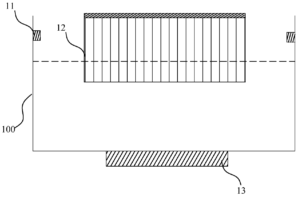
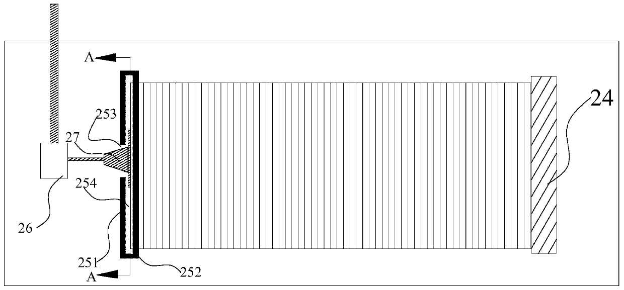
The invention discloses a degumming device and method of a cut silicon rod. The device comprises a cleaning unit and a degumming and splicing unit, wherein a spray assembly is arranged on the cleaningunit; the degumming and splicing unit is arranged downstream the cleaning unit, a heating assembly and hot water are arranged in the degumming and splicing unit, a bearing assembly is arranged abovethe degumming and splicing unit, the bearing assembly comprises a push plate and a protecting plate which are arranged at an interval, the push plate and the protecting plate are arranged on both endsof the cut silicon rod in the length direction of the cut silicon rod, the protecting plate can move in the length direction of the cut silicon rod, the protecting plate comprises a protecting platepart and a separating part which are connected, an opening which penetrates in the length direction of the cut silicon rod is formed in the protecting plate part, a sucking disc which is connected with a mechanical arm makes contact with the end of the cut silicon rod through the opening, the separating part is arranged on the upper end of one end, which is close to the push plate, of the protecting plate part, a containing clearance is formed between the separating part and the protecting plate part, the degumming and splicing unit further comprises an atomizing spray assembly, and the atomizing spray assembly is arranged above the containing clearance.

Description

technical field [0001] The invention belongs to the technical field of cutting and slicing silicon wafers, and in particular relates to a degumming device and method for silicon rods after cutting. Background technique [0002] In the related art, after the silicon wafer is cut, the cut silicon wafer needs to be cleaned and separated. The current degumming method after cutting is to soak the silicon wafer in hot water for about 20 minutes, and then manually separate and take the silicon wafer. In the existing degumming method, on the one hand, silicon powder or cutting mortar is likely to remain on the surface of the silicon wafer after degumming, which affects the progress of the subsequent process; The surface tension between the wafer and the silicon wafer is too strong, and it is easy to cause residual stress on the edge of the silicon wafer during the process of taking and dividing the wafer, resulting in chip (edge ​​chipping), and the labor efficiency is low, resultin...

Claims


Application Information

Patent Timeline
Patent Type & Authority Applications(China)
IPC IPC(8): B08B3/02B08B3/08B08B3/12B08B3/10B08B13/00B08B1/02B08B3/14B28D7/00
CPCB08B1/002B08B1/02B08B3/02B08B3/08B08B3/10B08B3/12B08B3/14B08B13/00B08B2203/007B08B2203/0217B28D5/0058
Inventor 陈建铭卢健平
Owner XUZHOU XINJING SEMICON TECH CO LTD
Why Eureka
Try Eureka