Induction welding production line of power module

A technology for power module and induction welding, which is applied in the direction of high-frequency current welding equipment, welding equipment, welding equipment, etc., which can solve the problem of long feeding path, long feeding time, inability to meet the sequential feeding of copper shell and bottom cover plate, and Placement and other issues to achieve the effect of shortening the path length, avoiding confusion and congestion, and overcoming difficulties in control

Active Publication Date: 2020-06-23
北京聚能合源科技有限公司
View PDF8 Cites 0 Cited by
  • Summary
  • Abstract
  • Description
  • Claims
  • Application Information

AI Technical Summary

Problems solved by technology

Although there are similar feeding mechanisms such as vibrating trays in the prior art, these existing devices cannot meet the sequential feeding and placement of copper shells and bottom cover plates.
Although the multi-degree-of-freedom manipulator can also realize the feeding of the copper shell and the bottom cover, the multi-degree-of-freedom movement of the multi-degree-of-freedom manipulator leads to a more sophisticated and complex control system, and the multi-dimensional movement of the multi-degree-of-freedom manipulator also directly leads to The feeding path is longer and the feeding time is longer

Method used


Image

  • Induction welding production line of power module
  • Induction welding production line of power module
  • Induction welding production line of power module

Examples


Embodiment Construction

[0034] The present invention will be further described in detail below in conjunction with the accompanying drawings, so that those skilled in the art can implement it with reference to the description.

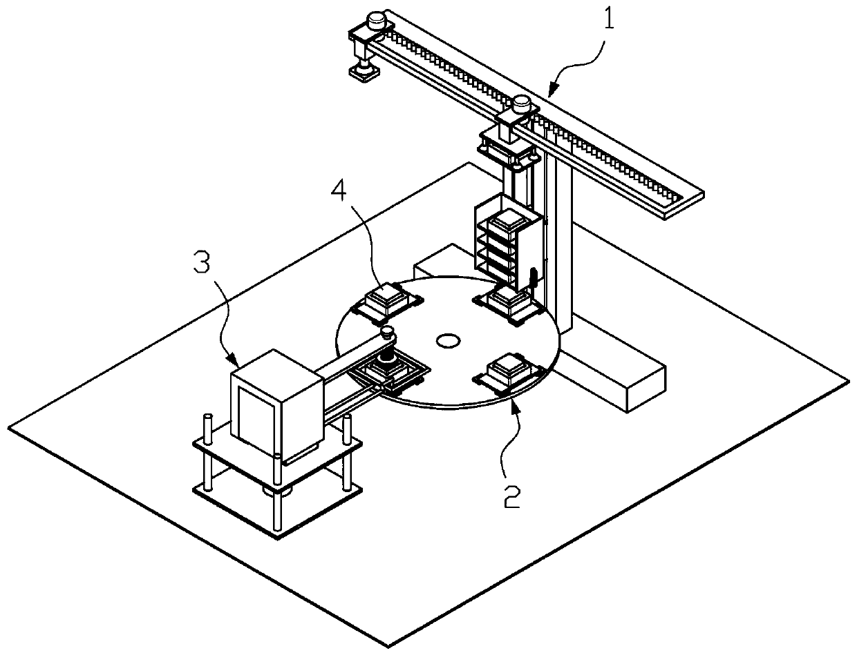
[0035] Such as figure 1 — Figure 11 As shown, the present invention provides an induction welding production line for power modules, including:

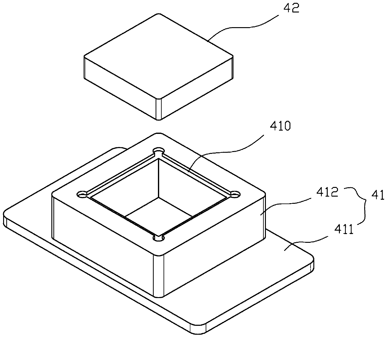
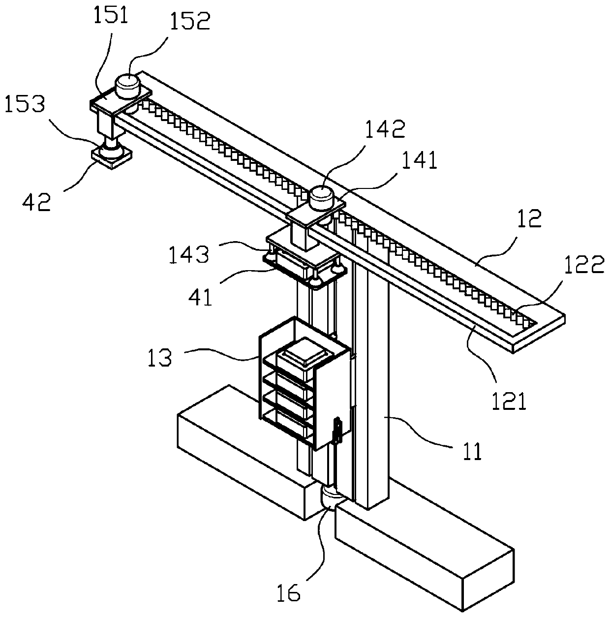
[0036] The batching unit 1 is capable of retrieving the shell 41 and the cover plate 42 respectively, and pairing them into a power module 4;

[0037] The jig unit 2 is used to carry and limit the power supply module 4 that falls from the batching unit 1; and

[0038] The welding unit 3 is capable of pressing the top of the power module 4 to be welded, and welding the shell 41 and the cover plate 42 into one;

[0039] Wherein, the jig unit 2 includes a rotatable material transfer plate 21 for guiding the power supply module 4 from the batching unit 1 to the welding unit 3 .

[0040] In the present invention, it uses the batching ...


PUM


Abstract

The invention discloses an induction welding production line of a power module. According to the induction welding production line of the power module, a transverse guide frame is arranged and provided with a first material taking assembly and a second material taking assembly, and the first material taking assembly and the second material taking assembly take materials from a shell and a cover plate correspondingly and move on the transverse guide frame in a reciprocating mode, namely main movement of the first material taking assembly and the second material taking assembly is horizontal movement, and the first material taking assembly and the second material taking assembly move in sequence, namely the first material taking assembly for performing material taking and placing to the shell arrives at a material conveying assembly on a vertical guide frame earlier than the second material taking assembly for performing material taking and placing to the cover plate; and in this way, the shell and the corresponding matched cover plate can be placed in the material conveying assembly arranged in a lifting mode in order, and due to the fact that the moving sequence is different, disorder and congestion of material taking can be avoided.

Description

technical field [0001] The invention relates to the technical field of power module production, in particular to an induction welding production line for power modules. Background technique [0002] Low-power power supply modules are usually composed of a copper shell and a bottom cover. The copper shell is filled with a module power supply part through heat-conducting glue, and the bottom cover is a printed circuit board that matches the module power supply part. Solder paste is applied. During the production process, the copper shell and the solder paste at the position of the copper-coated window of the printed circuit board need to be welded together. [0003] At present, the welding production of low-power power modules is mostly realized by electromagnetic induction welding. Before welding, the copper shell and bottom cover plate need to be placed on the corresponding jig, and the electromagnetic induction welding is realized by using the energized induction coil. Alt...

Claims


Application Information

Patent Timeline
Patent Type & Authority Applications(China)
IPC IPC(8): B23K13/01B23K13/00B23K37/04
CPCB23K13/00B23K13/01B23K37/0443B23K2101/36
Inventor 冯磊王兵曹邦武何波
Owner 北京聚能合源科技有限公司
Why Eureka
Try Eureka