
Liquid crystal display screen shearing processing equipment

A liquid crystal display and processing equipment technology, applied in glass manufacturing equipment, manufacturing tools, glass cutting devices, etc., can solve the problems of glass plate displacement, glass plate not found in time, and beveled edges.

Inactive Publication Date: 2020-06-23
吴早辉
View PDF0 Cites 0 Cited by
  • Summary
  • Abstract
  • Description
  • Claims
  • Application Information

AI Technical Summary

Problems solved by technology

[0003] After the glass plate is fixed, when cutting its edge, because the surface of the glass plate is smooth, when the cutting knife touches the glass plate, it is easy to cause the displacement of the glass plate. The displaced glass plate is not found in time. After that, there is a beveled edge phenomenon, which needs to be recalibrated and repaired

Method used


Image

  • Liquid crystal display screen shearing processing equipment
  • Liquid crystal display screen shearing processing equipment
  • Liquid crystal display screen shearing processing equipment

Examples


Embodiment 1

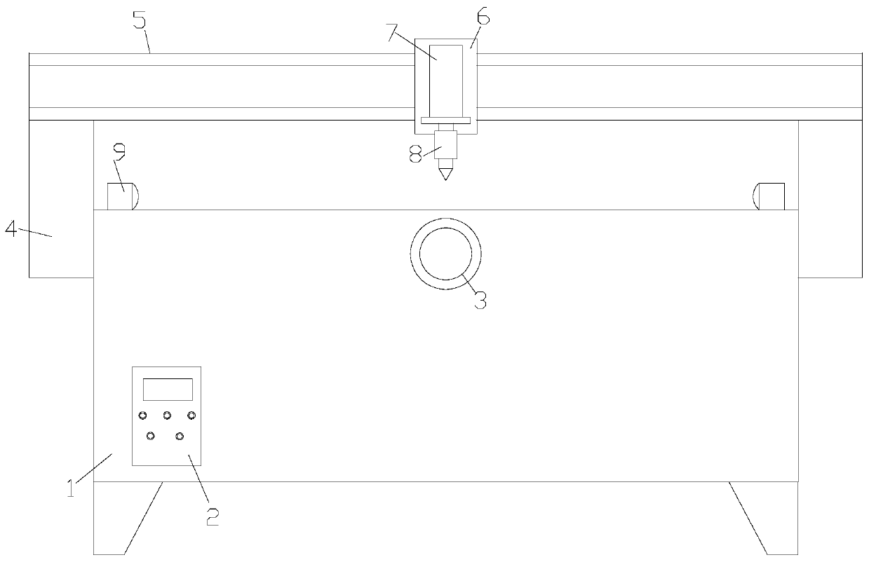
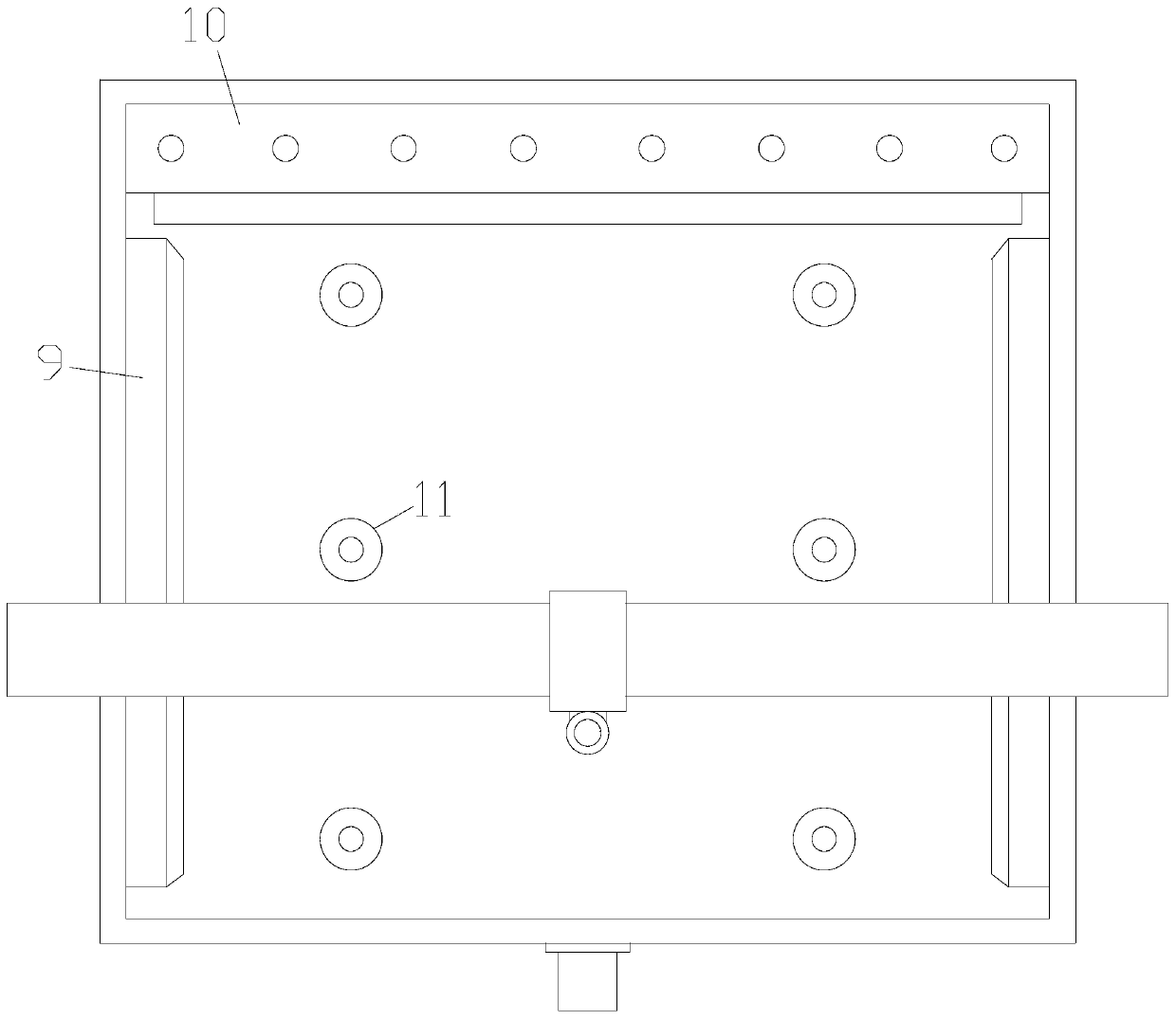
[0027] see Figure 1-Figure 5 , the present invention provides a liquid crystal display shearing processing equipment technical solution: its structure includes a workbench 1, a control box 2, a driving device 3, a front and rear moving frame 4, a lateral moving beam 5, a walking device 6, a lifting cylinder 7, a cutting 8, side clamp 9, the control box 2 is installed on the front of the workbench 1 through bolts, the front and rear moving frame 4 is installed on the left and right sides of the workbench 1 and the two are slidably matched, and the front and rear moving frame 4 is provided with a laterally moving beam 5 and a walking device 6 is provided on the laterally moving beam 5. The traveling device 6 is provided with a lifting cylinder 7 and a cutter 8. The left and right sides of the top end surface of the workbench 1 are Each activity is equipped with a side clamp 9, and the side clamp 9 is in transmission connection with the drive device 3 inside the workbench 1; Th...

Embodiment 2

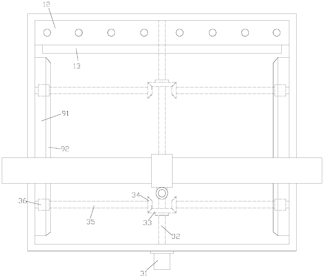
[0030] Such as image 3 As shown, on the basis of Embodiment 1, the driving device 3 is also composed of a motor 31, a rotating shaft 32, a main bevel gear 33, a driven gear 34, a screw mandrel 35 and a nut seat 36, and the motor 31 passes Bolts are installed on the end face of the front end of the workbench 1, one end of the rotating shaft 32 is connected with the motor 31, and the other end is connected with the inner wall of the rear end of the workbench 1. Screw mandrel 35, described screw mandrel 35 one ends are engaged with main bevel gear 33 on the rotating shaft 32 by driven gear 34, and the other end is fixed on the inner wall of workbench 1 left and right sides, and described screw mandrel 35 is provided with There is a nut seat 36 , and the side clamp 9 is composed of a splint 91 and a cushion 92 , the inner side of the splint 91 is provided with a cushion 92 , and the splint 91 is fixed above the nut seat 36 .

[0031] A driving device 3 is also installed inside t...


PUM


Abstract

The invention discloses liquid crystal display screen shearing processing equipment which structurally comprises a workbench, a control box, a driving device, a front-back moving frame, a transverse moving beam, a walking device, a lifting cylinder, a cutter and a side clamping device, the control box is installed on the front face of the workbench through bolts, and the front-back moving frame isinstalled on the left side and the right side of the workbench and is in sliding fit with the workbench. The liquid crystal display screen shearing processing equipment is advantageous in that a straightening device is mounted on the rear side of the workbench; the straightening device is composed of a straightening plate and a buzzer. When a glass plate inclines, the straightening plate can be squeezed to enable the squeeze head on the straightening plate to squeeze and deform an air cushion layer, so that an air bag ring in the air cushion layer is compressed, generated air flow flows out of the buzzing opening, the buzzing opening makes a sound, a worker is reminded to shut down for re-correction, and the phenomenon of bevel edges of the glass plate is prevented.

Description

technical field [0001] The invention is a liquid crystal display shearing processing equipment, which belongs to the technical field of shearing processing equipment. Background technique [0002] There is a layer of glass substrate in the liquid crystal display. This layer of glass substrate is cut out of the newly formed plate glass and cut into glass plates of various specifications and sizes. When cutting the glass, there are the following deficiencies: [0003] After the glass plate is fixed, when cutting its edge, because the surface of the glass plate is smooth, when the cutting knife touches the glass plate, it is easy to cause displacement of the glass plate. The displaced glass plate is not found in time. Finally, there is a beveled edge phenomenon, which needs to be recalibrated and repaired. Contents of the invention [0004] Aiming at the deficiencies existing in the prior art, the purpose of the present invention is to provide a liquid crystal display screen...

Claims


Application Information

Patent Timeline
IPC IPC(8): C03B33/023C03B33/03G02F1/13
CPCC03B33/023C03B33/03G02F1/1303
Inventor 吴早辉
Owner 吴早辉
Learn More