Eureka AIR delivers breakthrough ideas for toughest innovation challenges, trusted by R&D personnel around the world.

Medical sterilization drying equipment

A technology of drying equipment and sterilizing tank, which is applied in the field of medical sterilization and drying equipment, can solve the problems of easy damage of utensils, time-consuming and labor-intensive, etc., and achieve the effects of preventing skewing, good sterilization effect, and energy saving

Inactive Publication Date: 2019-01-29
自贡德西玛医疗设备有限公司
View PDF0 Cites 0 Cited by
  • Summary
  • Abstract
  • Description
  • Claims
  • Application Information

AI Technical Summary

Problems solved by technology

[0005] In view of the above-mentioned sterilization and drying are separate steps, resulting in time-consuming and labor-intensive, and the defect that the vessel is easily damaged in the process of handling, the purpose of the present invention is to provide a medical sterilization and drying equipment

Method used


Image

  • Medical sterilization drying equipment

Examples


Embodiment 1

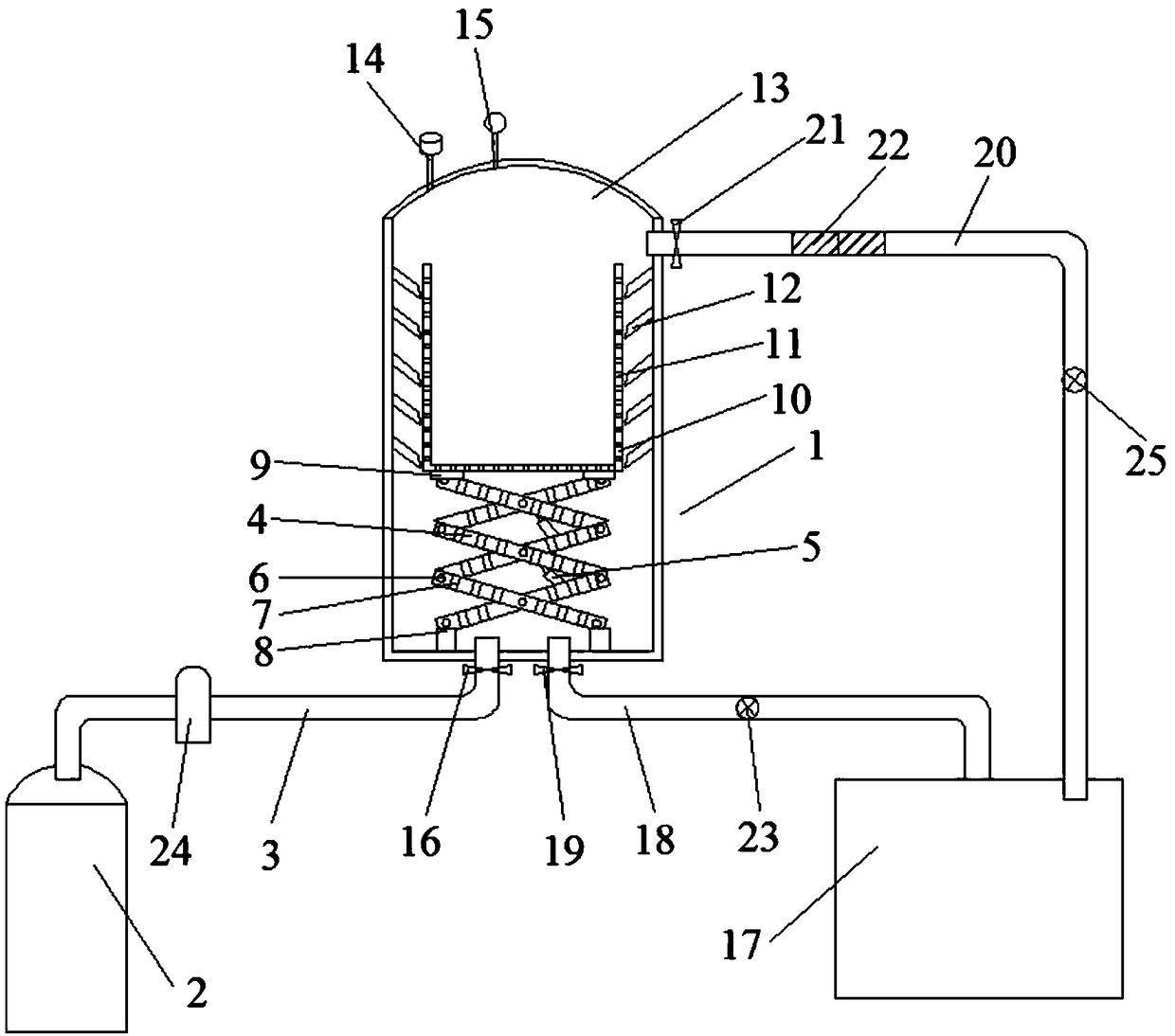
[0020] Such as figure 1 As shown, a medical sterilization and drying equipment includes a sterilization mechanism and a drying mechanism. The sterilization mechanism includes a sterilization tank 1 and a steam supply mechanism connected to the bottom of the sterilization tank 1. The drying The mechanism includes a heating air duct 18 communicating with the heating air box 17, the heating air duct 18 communicates with the bottom of the sterilization tank 1, and the heating air duct 18 is provided with a second A valve 19, a support mechanism is arranged in the sterilization tank 1, a sterilization basket 10 is arranged on the upper part of the support mechanism, and a plurality of third through holes 11 are arranged on the casing of the sterilization basket 10. The top of the sterilization tank 1 is provided with a detachable tank cover 13, and the tank cover 13 is provided with a safety valve 14 and an exhaust valve 15.

[0021] Working principle: open the tank cover 13, put ...

Embodiment 2

[0023] Based on Example 1, such as figure 1 As shown, the hot air circulation pipe 20 is also communicated with the hot air circulation pipe 17, and the hot air circulation pipe 20 communicates with the upper side of the sterilization tank 1, and the hot air circulation pipe 20 is provided with a third Valve 21 and second fan 25.

[0024] After drying for a period of time, open the third valve 21, and under the action of the second fan 25, the humid gas in the sterilization tank 1 is drawn out, and enters the heating air box 17 through the hot air circulation pipe 20 to be heated and reused to circulate the hot air Utilize, save energy.

Embodiment 3

[0026] Based on Example 1, such as figure 1 As shown, the hot air circulation pipe 20 is provided with at least one water-absorbing layer 22 .

[0027] The water-absorbing layer 22 absorbs the moisture in the humid gas, and the dried gas directly enters the heating air box 17 to be heated and utilized again.


PUM


Abstract

The invention discloses medical sterilization drying equipment, and belongs to the technical field of medical equipment. The medical sterilization drying equipment comprises a sterilization mechanismand a drying mechanism, the sterilization mechanism comprises a sterilization tank and a steam supply mechanism communicating with the bottom of the sterilization tank, the drying mechanism includes aheating bellows and a heating air duct communicating with the heating bellows, the heating air duct communicates with the bottom of the sterilization tank, a second valve is disposed at the heating air duct, a support mechanism is disposed in the sterilization tank, a sterilization basket is disposed on the upper portion of the support mechanism, a plurality of third through holes are disposed inthe basket body of the sterilization basket, the top of the sterilization tank is provided with a detachable tank cover, and the tank cover is provided with a safety valve and an exhaust valve. Utensils in the sterilization basket are sterilized and directly dried by the heating air duct communicating with the bottom of the sterilization tank and the heating bellows communicating with the heatingair duct and a first fan, time is saved, the working efficiency is high and the utensils are not be damaged.

Description

technical field [0001] The invention relates to the technical field of medical equipment, in particular to a medical sterilization and drying equipment. Background technique [0002] In hospitals, most medical utensils must be sterilized. Metal objects such as tweezers, scissors, and scalpels need to be sterilized by burning, disinfectant, and ultraviolet disinfection. However, glassware such as beakers, petri dishes, and test tubes are sterilized The disinfection effect of the method is not good, and the high-pressure steam sterilization method is generally used. [0003] High-pressure steam sterilization can kill all microorganisms including spores, and is currently the best and most widely used sterilization method. This is due to the strong penetrability of pure water vapor. Proteins and protoplast colloids are easily denatured and solidified under hot and humid conditions, and the enzyme system is easily destroyed. Moreover, steam will condense into water when it enter...

Claims


Application Information

Patent Timeline
Patent Type & Authority Applications(China)
IPC IPC(8): A61L2/07A61L2/26F26B21/04
CPCA61L2/07A61L2/26A61L2202/24F26B21/04
Inventor 邓述海
Owner 自贡德西玛医疗设备有限公司
Why Eureka
Eureka Blog
Learn More