
A stainless steel thin plate batch cutting equipment

A cutting equipment, stainless steel technology, applied in shearing machine equipment, metal processing equipment, shearing devices, etc., can solve the problems of low efficiency and low cutting accuracy, and achieve the purpose of avoiding scratches, ensuring cutting accuracy and reducing friction. Effect

Active Publication Date: 2022-04-22
佛山市鑫丰创盛金属制品有限公司
View PDF5 Cites 0 Cited by
  • Summary
  • Abstract
  • Description
  • Claims
  • Application Information

AI Technical Summary

Problems solved by technology

[0005] In order to overcome the need for people to judge the position of the stainless steel sheet with the naked eye, it is easy to cut the stainless steel sheet obliquely, the cutting accuracy is not high, and only one knife can be cut at a time, which is inefficient. The technical problem of the present invention is: to provide a cutting precision High and efficient stainless steel thin plate batch cutting equipment

Method used


Image

  • A stainless steel thin plate batch cutting equipment
  • A stainless steel thin plate batch cutting equipment
  • A stainless steel thin plate batch cutting equipment

Examples


Embodiment 1

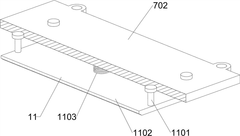
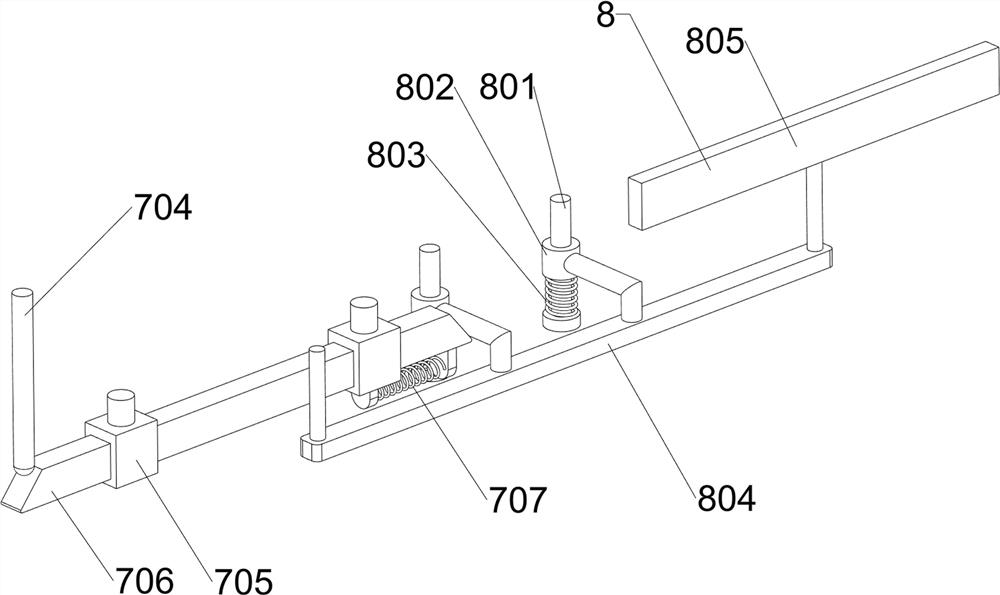
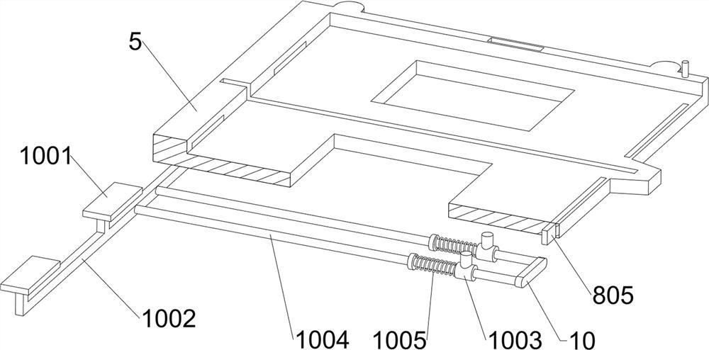
[0030] A stainless steel thin plate batch cutting equipment, such as Figure 1-6 As shown, it includes a base plate 1, a frame 2, a cylinder 3, a drive assembly 4, an installation frame 5, a cutting assembly 6, a transmission assembly 7 and a limit assembly 8, and the top of the base plate 1 is connected with the frame 2 and the installation frame 5. The frame 2 is located at the rear side of the installation frame 5, the cylinder 3 is installed on the top of the frame 2, the driving assembly 4 is installed on the frame 2, the cutting assembly 6 and the transmission assembly 7 are installed on the installation frame 5, and the limiter is installed on the bottom of the installation frame 5. Component 8.

[0031] When it is necessary to cut the stainless steel sheet, people put the stainless steel sheet in the installation frame 5, and then control the extension of the cylinder 3, and the cylinder 3 drives the drive assembly 4 to work, and the drive assembly 4 drives the limit a...

Embodiment 2

[0041] On the basis of Example 1, such as image 3 , Figure 4 , Figure 5 , Figure 7 and Figure 8 As shown, an auxiliary assembly 9 is also included. The auxiliary assembly 9 includes a second support frame 901, a mounting plate 902, a guide roller 903 and a fifth spring 904. The bottom of the installation frame 5 is slidingly provided with a second support frame 901, and the second Four mounting plates 902 are connected to the top of the support frame 901, and a plurality of guide rollers 903 are installed on the top of each mounting plate 902. The guide rollers 903 pass through the mounting frame 5, and the second mounting plate 901 is connected between the mounting frame 5 and the second support frame 901. Five springs 904.

[0042] People put the stainless steel sheet into the installation frame 5, the stainless steel sheet rolls on the guide roller 903, reduces the frictional force, plays a protective role to the stainless steel sheet, avoids the stainless steel sh...


PUM


Abstract

The invention relates to a cutting device, in particular to a stainless steel thin plate batch cutting device. The technical problem of the present invention is: to provide a stainless steel thin plate batch cutting equipment with high cutting precision and high working efficiency. Technical solution: A batch cutting equipment for stainless steel thin plates, including a bottom plate, a frame and an installation frame are installed on the upper side of the bottom plate; a cylinder, the cylinder is installed on the upper side of the frame; a drive assembly, the drive The components are installed on the frame, and the drive components are used to provide power. The invention can block the stainless steel sheet through the limiting component, which plays a positioning role, avoids the stainless steel sheet from being cut obliquely, ensures the cutting accuracy, and can cut three times at one time, with high efficiency; the friction force can be reduced through the auxiliary component, and the stainless steel The sheet plays a protective role to prevent the stainless steel sheet from being scratched.

Description

technical field [0001] The invention relates to a cutting device, in particular to a stainless steel thin plate batch cutting device. Background technique [0002] Stainless steel sheet is an alloy plate that is not easy to rust. It has high toughness and mechanical strength, and is difficult to be corroded by alkaline gas and solution. It is widely used in the production of mechanical equipment parts. Because stainless steel sheet is relatively large, it is The stainless steel sheet needs to be cut during use. [0003] Nowadays, people usually put the stainless steel sheet on the cutting machine, and then manually control the cutting machine to cut the stainless steel sheet. At present, most of the cutting machines do not have the function of positioning, and people need to judge the position of the stainless steel sheet with the naked eye, so that it is easy to cut the stainless steel sheet. The cutting is oblique, the cutting accuracy is not high, and only one knife can ...

Claims


Application Information

Patent Timeline
Patent Type & Authority Patents(China)
IPC IPC(8): B23D15/06B23D33/02
CPCB23D15/06B23D33/02
Inventor 廖跃龙
Owner 佛山市鑫丰创盛金属制品有限公司
Learn More