Mid-span damping type stepless self-locking pushing device for flat-turning opening bridge

A push-up device and shock-absorbing technology, applied in springs/shock absorbers, bridges, suspension bridges, etc., can solve problems such as inability to achieve stepless connection, wear, and affecting the normal operation of bridges.

Inactive Publication Date: 2020-06-23
何政洋 +2
View PDF0 Cites 0 Cited by
  • Summary
  • Abstract
  • Description
  • Claims
  • Application Information

AI Technical Summary

Problems solved by technology

[0002] The mid-span connection of existing swing open bridges generally adopts the traditional bolt structure. Due to the braking of the vehicles on the bridge and the heavy load of the vehicles, a large horizontal force and a vertical load will be generated. Although the traditional bolts can bear the horizontal , vertical load, but under the condition of huge horizontal force and heavy load impact, the traditional bolt structure is easy to break, wear, glue damage and inconvenient maintenance, and it cannot realize stepless connection, which seriously affects the normal operation of the bridge
The mid-span connection of the swing open bridge is a common and serious problem. When the vehicle passes the bridge, it is easy to cause the bridge to twist, fatigue damage, and even cause the bridge to break in severe cases.

Method used


Image

  • Mid-span damping type stepless self-locking pushing device for flat-turning opening bridge
  • Mid-span damping type stepless self-locking pushing device for flat-turning opening bridge
  • Mid-span damping type stepless self-locking pushing device for flat-turning opening bridge

Examples


Embodiment Construction

[0021] All features disclosed in this specification, or steps in all methods or processes disclosed, can be combined in any way, except for mutually exclusive features and steps.

[0022] Any feature disclosed in this specification, unless specifically stated, can be replaced by other alternative features that are equivalent or have similar purposes. That is, unless expressly stated otherwise, each feature is one example only of a series of equivalent or similar features.

[0023] The structure and principle of the mid-span stepless shock-absorbing self-locking jacking device of the horizontal swing open bridge of the present invention will be described in detail below.

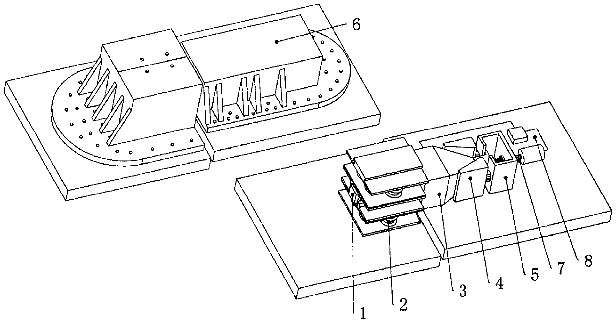
[0024] figure 1 A schematic diagram of the overall structure of the mid-span shock-absorbing type stepless self-locking jacking device of the horizontal swing opening bridge according to the present invention is shown. The mid-span shock-absorbing stepless self-locking thrusting device of the horizontal sw...


PUM


Abstract

The invention discloses a mid-span damping type stepless self-locking pushing device of a flat-turning opening bridge. The mid-span damping type stepless self-locking pushing device is composed of a bridge pushing structure, a stepless self-locking structure, a bridge damping device, a stepping motor servo system and a box body; the bridge damping structure is located on the left side of a bridge;the stepless self-locking structure is located on the right side of the bridge; the bridge pushing structure is located between the bridge damping structure and the stepless self-locking structure; and the stepping motor servo system is located on one side of the stepless self-locking structure of the bridge. The bridge pushing structure comprises a floating block and a pushing rod; the floatingblock contacts with a left box body to achieve horizontal force transmission; the pushing rod is connected with the floating block to transmit horizontal force to a right wedge block; and therefore, self-locking is achieved through the friction pair of the wedge block and the box body. The bridge damping structure comprises a spring baffle, a high-strength spring and a viscous damper. The balancedamping of the bridge is achieved through the high-strength spring and the viscous damper, and the pushing structure can work stably and effectively. The stepless self-locking structure comprises a wedge block, an ejector rod and a box body; and a stepless self-locking function is achieved through a special treatment friction pair. The lead screw of the stepping motor servo system is connected with a sliding box body, so that the sliding function of the pushing rod and the unlocking function of the self-locking structure are achieved; the box body is effectively connected with the bridge floorthrough high-strength friction type bolts. According to the device, a left bridge and a right bridge can be connected through the damping type stepless self-locking pushing device, and loads are stably and effectively transmitted. The device is simple in structure, excellent in bearing performance, high in safety coefficient and low in cost.

Description

technical field [0001] The invention relates to the technical field of bridge traffic, more specifically, to a shock-absorbing stepless self-locking jacking device for bridge mid-span structures. Background technique [0002] The mid-span connection of the existing swing open bridge generally adopts the traditional bolt structure. Due to the braking of the vehicles on the bridge and the heavy load of the vehicle, a large horizontal force and a vertical load will be generated. Although the traditional bolt can bear the horizontal , vertical load, but the traditional bolt structure is easy to break, wear, glue damage and inconvenient maintenance under the condition of huge horizontal force and heavy load impact, and it cannot realize stepless connection, which seriously affects the normal operation of the bridge. It is a common and serious problem to connect the mid-span of the swing open bridge. When the vehicle passes the bridge, it is easy to cause the distortion of the bri...

Claims


Application Information

Patent Timeline
Patent Type & Authority Applications(China)
IPC IPC(8): E01D15/04E01D19/00F16F15/02
CPCE01D15/04E01D19/00F16F15/022
Inventor 何政洋张芸金徐玖林牟磊姚锐
Owner 何政洋
Why Eureka
Try Eureka