Eureka AIR delivers breakthrough ideas for toughest innovation challenges, trusted by R&D personnel around the world.

Rocker potentiometer

A potentiometer and rocker technology, applied in the field of potentiometers, can solve problems such as poor elastic reset ability, small size, and poor hand feeling

Pending Publication Date: 2020-06-23
东莞市宏泽电子有限公司
View PDF1 Cites 0 Cited by
  • Summary
  • Abstract
  • Description
  • Claims
  • Application Information

AI Technical Summary

Problems solved by technology

[0004] However, the rocker potentiometer also has the following shortcomings: the upper rocker arm and the lower rocker arm of the patent 201920677339.3 both use the torsion spring structure to achieve rocking and elastic reset. Due to the limitations of the torsion spring structure itself, this adoption The rocker potentiometer with torsion spring structure can only shake the rocker for about 100,000 times, and the service life is still not long enough; at the same time, the rocker potentiometer with torsion spring structure, its upper rocker arm and lower rocker arm The elastic reset ability of the rocker is poor, and it is easy to cause poor re-centering performance of the rocker, and there is still the problem that the change of the rocking range of the rocker and the change of the rocking force of the rocker are difficult to achieve synchronous increase or decrease, and the hand feeling is poor. ; In addition, the detection components are located on one side of the upper rocker arm and the lower rocker arm, and the stability and accuracy are not high enough

Method used


Image

  • Rocker potentiometer
  • Rocker potentiometer
  • Rocker potentiometer

Examples


Embodiment Construction

[0019] The structural principle and working principle of the present invention will be further described in detail below in conjunction with the accompanying drawings.

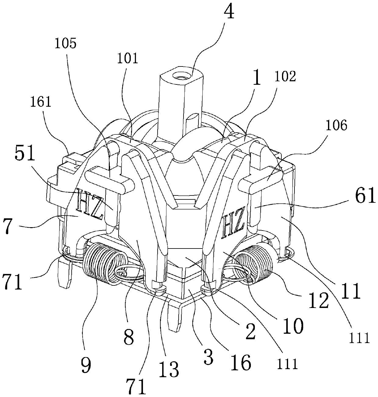
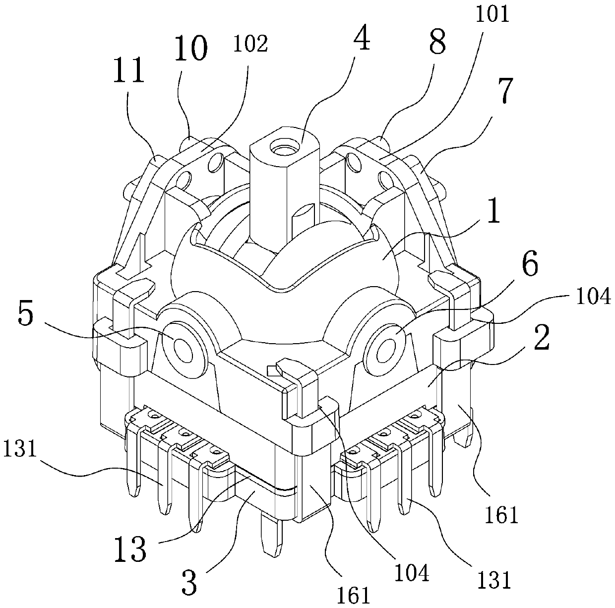
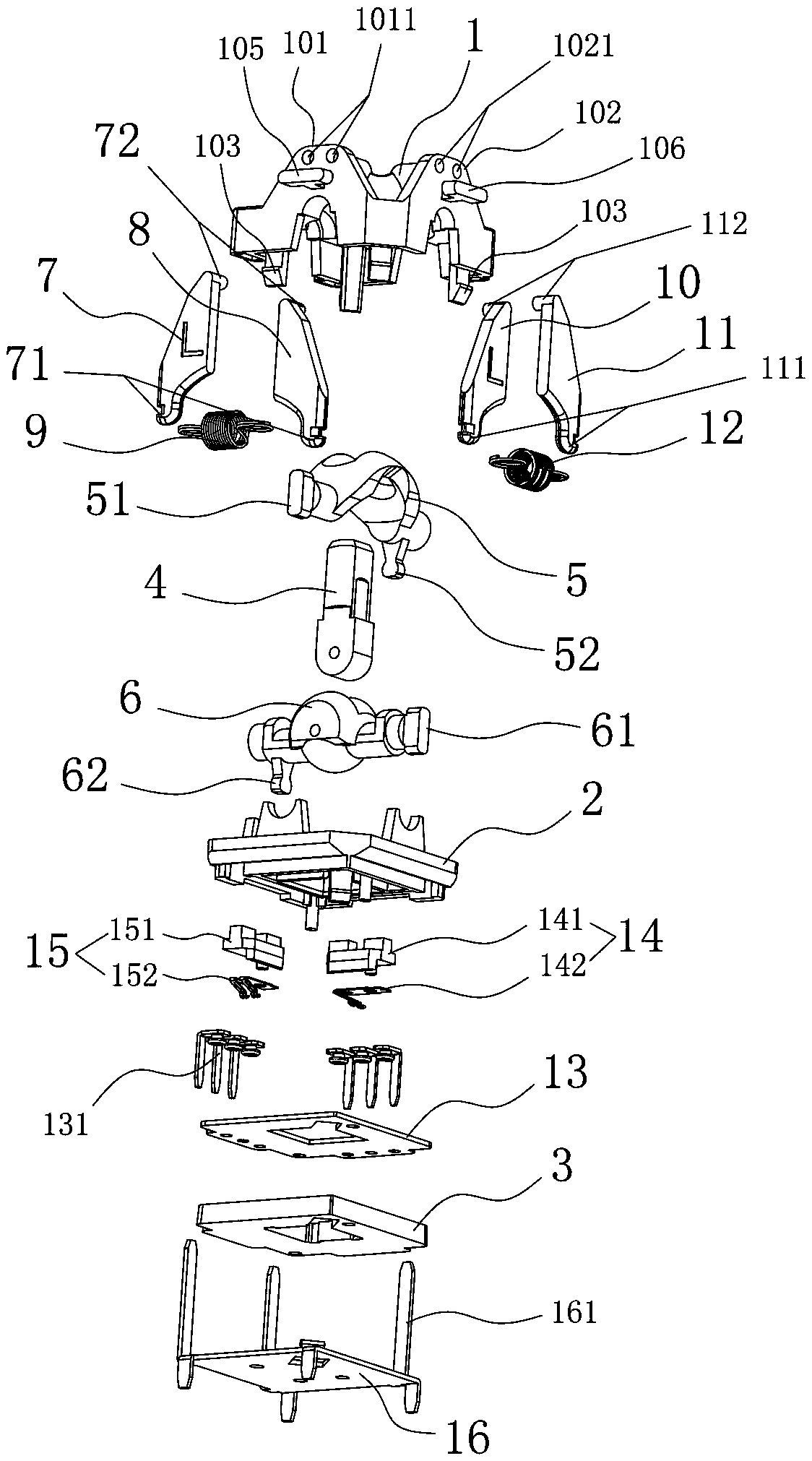
[0020] Such as Figure 1-Figure 4 As shown, the present invention is a rocker potentiometer, comprising an upper cover 1, a middle cover 2, a lower cover 3, a rocker 4, an upper rocker arm 5, a lower rocker arm 6, a first left spring arm 7, a first right Spring arm 8, first spring 9, second left spring arm 10, second right spring arm 11, second spring 12, carbon sheet 13, first brush mechanism 14, second brush mechanism 15; the upper cover 1 and the middle cover 2 are closed together to form an upper chamber; the lower rocker arm 6 is arranged in the upper chamber, and the lower rocker arm 6 is rotationally connected with the middle cover 2 and the upper cover 1; the upper rocker arm 5 is arranged in the upper chamber Among them, the upper rocker arm 5 is in sliding contact with the lower rocker arm 6, and the ...


PUM


Abstract

The invention discloses a rocker potentiometer which comprises an upper cover, a middle cover, a lower cover, a rocking handle, an upper rocker arm, a lower rocker arm, a first left spring arm, a first right spring arm, a first spring, a second left spring arm, a second right spring arm, a second spring, a carbon plate, a first electric brush mechanism and a second electric brush mechanism. The upper cover is provided with a first positioning plate and a second positioning plate; the upper ends of the first left spring arm and the first right spring arm are rotatably connected with the first positioning plate; the first spring is connected between the lower ends of the two spring arms; one end of the upper rocker arm is provided with a first poking piece clamped between the two spring arms, and the other end of the upper rocker arm is provided with a first poking rod; the upper ends of the second left spring arm and the second right spring arm are rotatably connected with the second positioning plate, the second spring is connected between the lower ends of the two spring arms; and one end of the lower rocker arm is provided with a second poking piece clamped between the two springarms, and the other end of the lower rocker arm is provided with a second poking rod. The rocker potentiometer is long in service life, the rocking handle is good in centering performance, the rocking handle is good in rotating hand feeling, and stability and precision are high.

Description

technical field [0001] The invention relates to the technical field of potentiometers, in particular to a rocker potentiometer. Background technique [0002] The rocker potentiometer is a variable potentiometer suitable for the joystick control handle of game consoles, drones, etc. By shaking the rocker of the rocker potentiometer, and then adjusting the resistance value through the brush mechanism of the potentiometer, Realize the control of the state changes of internal related components such as game consoles and drones. In the prior art, the disadvantages of the rocker potentiometer are that the service life is not long enough, the rocker has poor re-neutrality, the installation structure of the brush is not reasonable enough, the accuracy is poor, the hand feeling of the rocker is poor, and the rocker is shaken. It is difficult for the variation of the deviation range to be larger or smaller synchronously with the variation of the force of shaking the joystick. [000...

Claims


Application Information

Patent Timeline
Patent Type & Authority Applications(China)
IPC IPC(8): H01C10/32H01C1/00
CPCH01C10/32H01C1/00
Inventor 曾国生梁成腾黄胜开黄国忠
Owner 东莞市宏泽电子有限公司
Why Eureka
Eureka Blog
Learn More