
Gear milling machine

A technology for a gear milling machine and a machine body is applied in the field of gear milling machines, which can solve the problems of high production cost, low product quality, and easy damage to the cutter head of the gear milling machine.

Active Publication Date: 2020-06-26
南京回转支承机械有限公司
View PDF12 Cites 0 Cited by
  • Summary
  • Abstract
  • Description
  • Claims
  • Application Information

AI Technical Summary

Problems solved by technology

[0003] The Chinese patent with the authorized announcement number CN205816976U discloses a gear milling machine with a milling cutter lifting device, which solves the technical problems of the existing gear milling machine that the cutter head is easily damaged, the product quality is low, and the production cost is high. The base, the base is provided with a column, the column is equipped with a milling cutter lifting device and a milling cutter rotating device, the milling cutter lifting device is equipped with a lifting motor, a slide rail and a lifting plate, the lifting motor and the slide rail are all set on the column, and the lifting plate There is a slideway, the slideway is matched with the slide rail, and the lifting motor is connected with the lifting plate
[0004] When using the gear milling machine in the prior art, the milling cutter mills the workpiece, and the disc drives the workpiece to rotate, and the milling cutter continues to mill the workpiece. However, in practical applications, the milling cutter mills from top to bottom to form Tooth groove, the top of the tooth near the two sides of the tooth groove produces relatively sharp edges. At this time, after the gear needs to be disassembled, the sharp edge of the tooth top should be chamfered again by a gear chamfering machine, which is time-consuming and laborious, and needs to be improved

Method used


Image

  • Gear milling machine
  • Gear milling machine
  • Gear milling machine

Examples


Embodiment

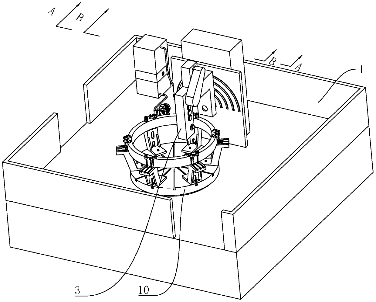
[0068] refer to figure 1 , a gear milling machine, including a body 1, the body 1 is respectively provided with a column 3 and a workbench 10.

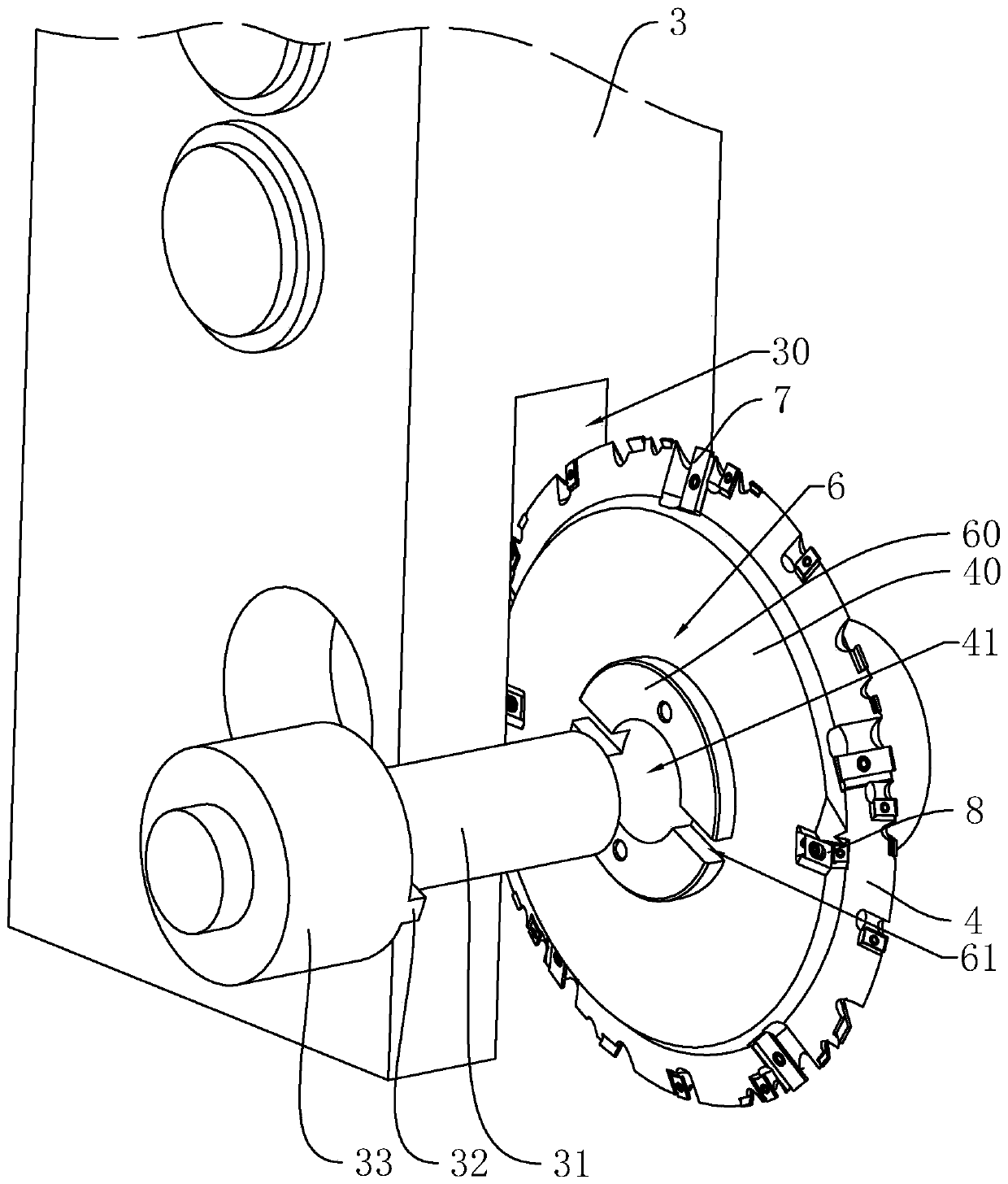
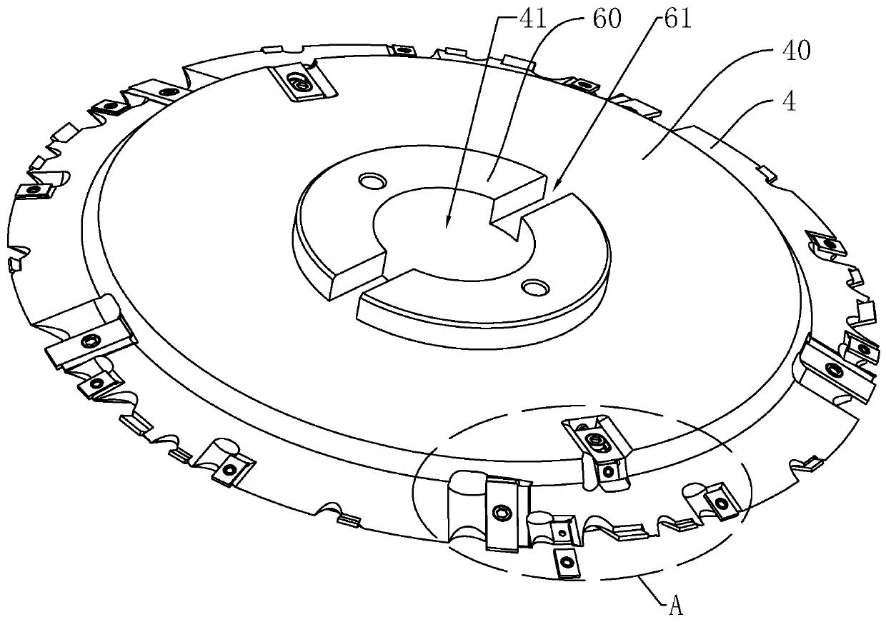
[0069] refer to figure 2 , the bottom wall of the column 3 is provided with a fixed gap 30, the side wall of the fixed gap 30 is rotated with a positioning shaft 31, and the positioning shaft 31 is provided with two fixed sleeves 33, and the fixed sleeve 33 is fixedly connected with the positioning shaft 31. Two protrusions 32 are arranged on the opposite side walls of the fixed sleeve 33, and a cutter body 4 is fixedly arranged on the side wall of the positioning shaft 31. Bosses 40 are arranged on opposite sides of the cutter body 4, and the diameter of the bosses 40 is Less than the diameter of the cutter body 4, the side wall of the boss 40 is provided with a mounting hole 41 for the positioning shaft 31 to pass through, and the side of the boss 40 away from the cutter body 4 is provided with two half ring plates 60, and the two...


PUM


Abstract

The invention discloses a gear milling machine, and relates to gear machining equipment. The gear milling machine aims to solve the problems that chamfers of gear tooth crests formed by milling cuttermilling need remachining and the efficiency is low in the prior art, according to the key point of the technical scheme, the gear milling machine comprises a machine body, a stand column arranged onthe machine body and a cutter body rotatably arranged on the stand column, a fixed notch for installing the cutter body is formed in the stand column, and a positioning shaft is rotatably arranged onthe side wall of the fixed notch. Bosses are arranged on the two sides, deviating from each other, of the cutter body, installation holes for the positioning shaft penetrating through are formed in the side walls of the bosses, cutting cutter groups for cutting gear grooves are arranged at the edges and the two sides, deviating from each other, of the cutter body, and chamfer cutters are arrangedon the two sides, deviating from each other, of the bosses; twice machining can be combined into once machining, and the working efficiency is improved; and the gear meshing precision can further be improved.

Description

technical field [0001] The present invention relates to a gear machining equipment, more specifically, it relates to a gear milling machine. Background technique [0002] Gear milling machine is the most widely used machine tool in gear processing machine tools, that is, the tooth surface of gear or rack can be processed by using milling cutter or milling cutter disc according to the forming method or generating method, and straight teeth, helical gears can be cut on the gear milling machine. Toothed cylindrical gears can also process worm gears, sprockets, etc. Since the milling cutter mainly rotates, supplemented by the feed motion of the table or milling head, the workpiece can obtain the required processing surface; its main components include the machine body , table, column, milling cutter, drive unit and cooling unit. [0003] The Chinese patent with the authorized announcement number CN205816976U discloses a gear milling machine with a milling cutter lifting device,...

Claims


Application Information

Patent Timeline
IPC IPC(8): B23F5/20B23F19/10B23F23/00B23F23/06
CPCB23F5/20B23F19/10B23F23/00B23F23/06
Inventor 黄厚平黄士海
Owner 南京回转支承机械有限公司
Learn More