Swing conveying device and body-in-white conveying line

A technology of conveying device and double rocker arm, applied in the direction of lifting device, auxiliary device, lifting frame, etc., can solve the problems such as affecting the working efficiency of automatic production line, complicated structure of conveying equipment, inconvenient maintenance, etc., saving handling time and high handling efficiency. , cost-saving effect

Pending Publication Date: 2020-06-26
烟台宇信科技有限公司
View PDF0 Cites 0 Cited by
  • Summary
  • Abstract
  • Description
  • Claims
  • Application Information

AI Technical Summary

Problems solved by technology

However, the efficiency of this type of handling equipment is slow, because the transportation to the next station requires three processes of rising, translation, and falling, and this type of conveying equipment is mostly driven by motors, and the linear motion in three different directions is driven by the motor. Rotary motion becomes linear motion, and each process requires corresponding motion conversion devices, such as rack and pinion, sprocket chain, etc., resulting in complex structure of conveying equipment, high cost, and inconvenient maintenance. Motors are required for each of the above processes Start to accelerate, run at an even speed, decelerate to stop, and finely position the handling equipment. The handling process consists of three discontinuous processes. There are three motor operating cycles. Long time will affect the work efficiency of the automated production line.

Method used


Image

  • Swing conveying device and body-in-white conveying line
  • Swing conveying device and body-in-white conveying line
  • Swing conveying device and body-in-white conveying line

Examples


Embodiment Construction

[0057] The principles and features of the present invention are described below in conjunction with examples, which are only used to explain the present invention and are not intended to limit the scope of the present invention.

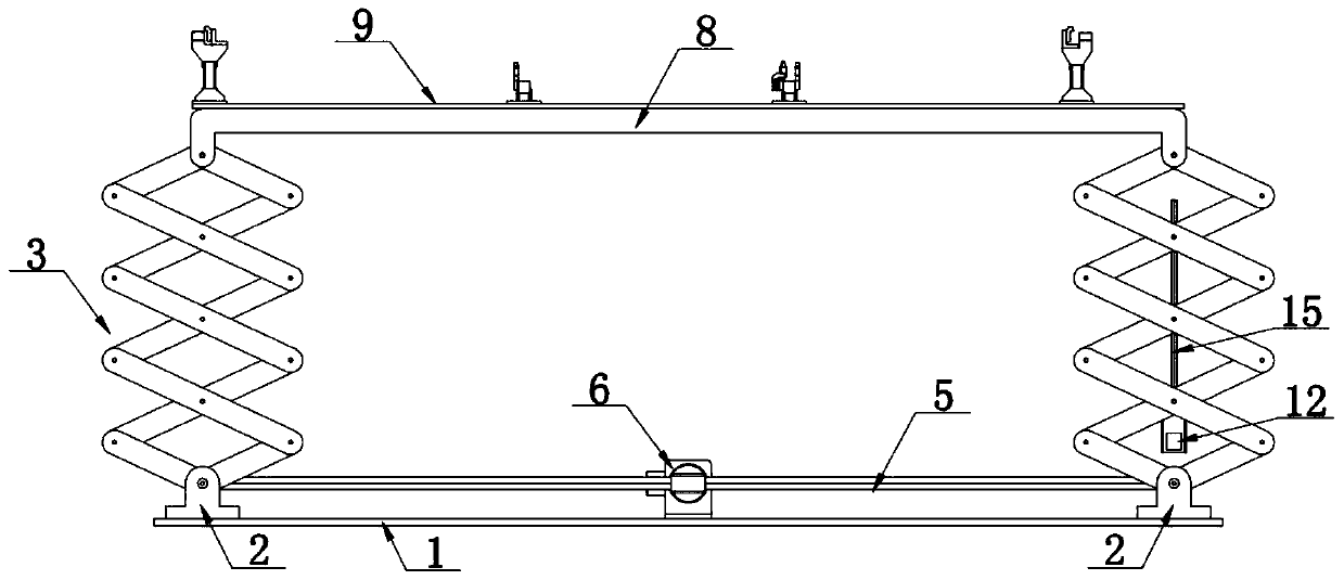
[0058] Such as Figure 3-Figure 17 As shown, a swing conveying device includes at least one double rocker arm mechanism, a power mechanism for driving the double rocker arm mechanism to swing, and a telescopic drive mechanism for driving the double rocker arm mechanism to expand and contract;

[0059] The double rocker arm mechanism includes a base plate 1, a load plate 9, left and right scissor rocker arm mechanisms and a transmission mechanism arranged between the base plate and the load plate. The transmission shaft 4 at the end, the transmission shaft 4 is rotatably installed on the bottom plate, the transmission shaft 4 is connected with the drive shaft 5 through the synchronous commutator 7, and the drive shaft 5 is under the action of the powe...


PUM


Abstract

The invention discloses a swing conveying device and a body-in-white conveying line. The swing conveying device comprises at least one double-rocker-arm mechanism, a power mechanism and a telescopic driving mechanism, the double-rocker-arm mechanism comprises a bottom plate, a bearing plate, a left shear type rocker arm mechanism, a right shear type rocker arm mechanism and a transmission mechanism, the transmission mechanism comprises a driving shaft and a transmission shaft, the power mechanism comprises a swing servo motor, and an output shaft of the swing servo motor is connected with thedriving shaft; each shear-type rocker arm mechanism comprises two shear-type rocker arm units arranged side by side, the tops of the shear-type rocker arm units are hinged to the bearing plate, and the bottoms of the shear-type rocker arm units are in key connection with the transmission shaft. According to the swing conveying device and the body-in-white conveying line, one servo motor is used for driving the double-rocker-arm mechanism to swing, carrying between stations is achieved, telescopic servo motors are arranged between the shear type rocker arm units, the extension and retraction ofthe shear-type rocker arm units are achieved, the two servo motors cooperate with each other to carry out carrying according to the translation distance and the lifting height of vehicle models, thecarrying position precision is high, the stabilization is achieved, and the carrying efficiency is high; and carrying operation of stamping parts among the welding stations can be completed, and thecost is saved.

Description

technical field [0001] The invention relates to a swing conveying device and a body-in-white conveying line, belonging to the technical field of automobile welding conveying lines. Background technique [0002] At present, in the automatic welding production line in the automobile welding workshop, after the body-in-white is welded at one station, it needs to be transported to the next station for welding. The high efficiency, stability and accuracy of the conveying equipment become very important, such as figure 1 Shown is the BIW positioning support fixture with 4 stations. Each station has corresponding welding spots for welding. After the welding of the current station is completed, the BIW is transported from the current station to the next one, and then the next step is carried out. For the welding of solder joints at one station, the number of stations should be planned in advance according to the vehicle model, cycle time, and welding tongs speed. [0003] The exist...

Claims


Application Information

Patent Timeline
Patent Type & Authority Applications(China)
IPC IPC(8): B66F7/06B66F7/28B23K37/00
CPCB23K37/00B66F7/0666B66F7/0683B66F7/28
Inventor 孔瑜伟
Owner 烟台宇信科技有限公司
Why Eureka
Try Eureka