
Plug-in residual current load current sensor of miniature circuit breaker

A miniature circuit breaker and residual current technology, applied in the direction of measuring current/voltage, only measuring current, instruments, etc., can solve problems such as increasing product volume, no sensor installation, and impact on circuit breaker performance, so as to ensure installed capacity and simple structure Reasonable, easy-to-test effects

Pending Publication Date: 2020-06-26
上力电力科技有限公司
View PDF0 Cites 0 Cited by
  • Summary
  • Abstract
  • Description
  • Claims
  • Application Information

AI Technical Summary

Problems solved by technology

To achieve the above added functions, because the structure of the miniature circuit breaker itself has no fundamental innovation in industry technology, the installation positions of various sensors will have an impact on the performance of the original circuit breaker
[0003] At present, in the known field, the miniature residual current protection circuit breaker is to add a shell at the outlet end of the miniature circuit breaker, and install the residual current sensor; add a general 2P leakage module (residual current signal processing and execution module) on the side of the circuit breaker , lengthen the original outgoing wire, and then lead it to the residual current signal processing and execution module after passing through the residual current sensor, which not only increases the volume of the product, but also greatly improves the requirements for the manufacturing process in production, and also increases the difficulty of quality control , especially for the emerging IoT miniature circuit breakers, there is basically no better way to implement the installation of numerous sensors

Method used


Image

  • Plug-in residual current load current sensor of miniature circuit breaker
  • Plug-in residual current load current sensor of miniature circuit breaker
  • Plug-in residual current load current sensor of miniature circuit breaker

Examples


Embodiment Construction

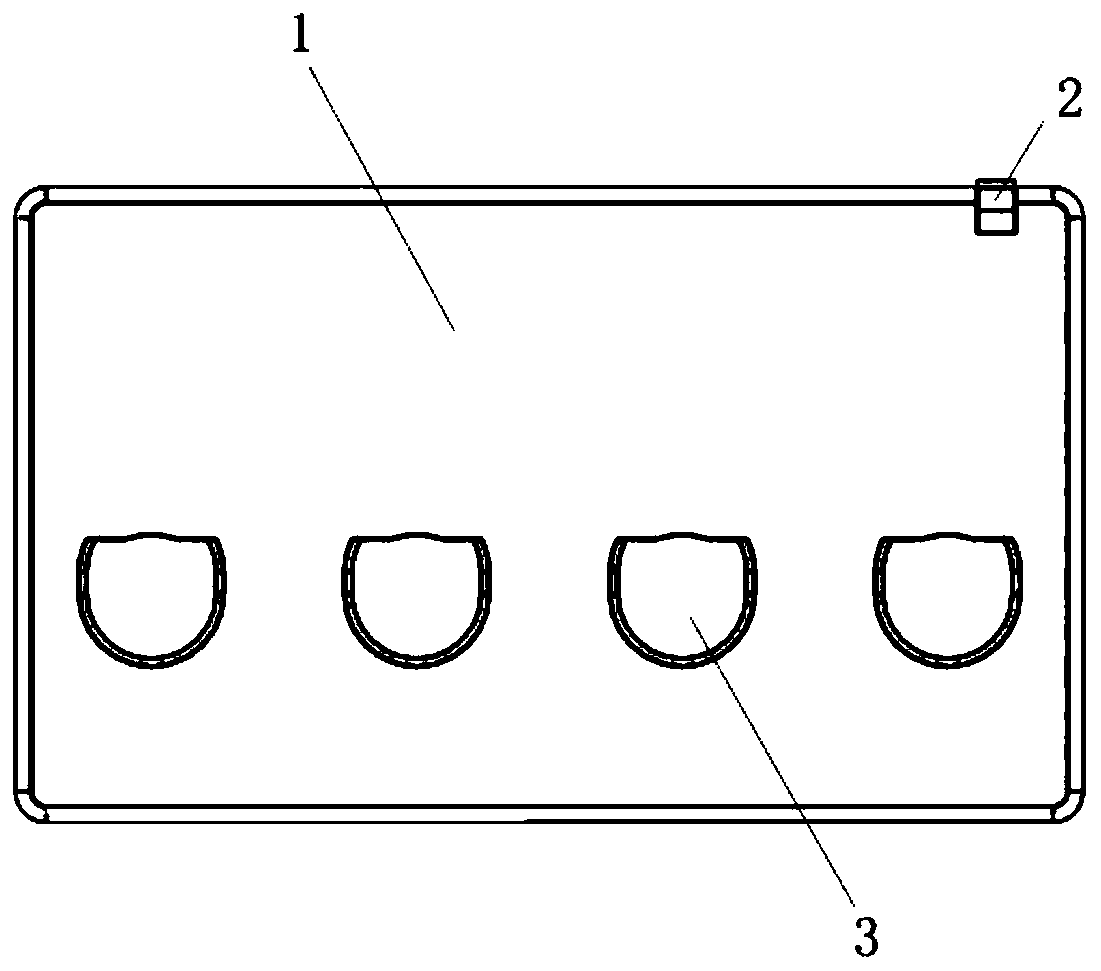
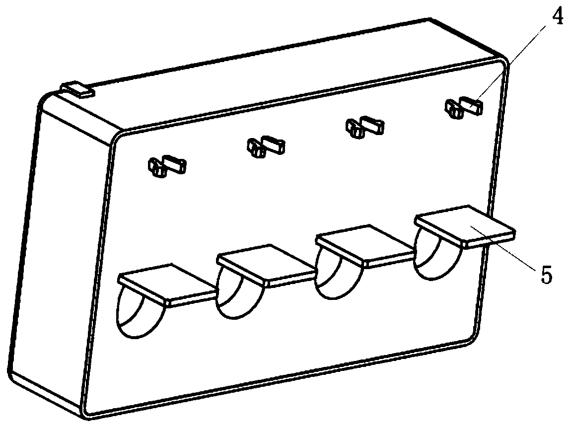
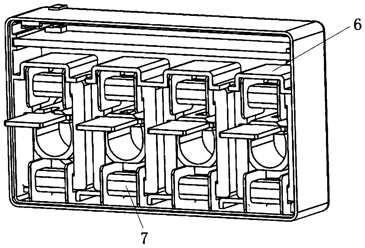
[0020] As shown in the accompanying drawings, a miniature circuit breaker plug-in residual current load current sensor includes a sensor body 1, a jack 3 is opened in the middle of the sensor body 1, and a light guide test jumper is installed on the upper side of the body The button 2, the back of the sensor body 1 is equipped with a plurality of buckles 4, four copper sheets 5 are installed under the buckles 4, and the copper sheets 5 are located at the upper end of the jack 3, and the inside of the sensor body 1 A fixing part 7 is installed, and the upper end of the fixing part 7 is equipped with a contact part 6;

[0021] Wherein, the sensor main body 1 realizes plug-in installation through the copper sheet 5, which reduces the shielding of the signal due to the structure of the circuit breaker body, electrical isolation, arc interference and metal parts;

[0022] The sensor main body 1 is installed at the front and rear ends of the circuit breaker, and the thickness is onl...


PUM


Abstract

The invention discloses a plug-in residual current load current sensor of a miniature circuit breaker. The sensor comprises a sensor body, wherein a jack is formed in the middle of the sensor body, alight guide trial jump button is arranged on one side above the sensor body, a plurality of buckles are arranged on the back surface of the sensor body, four copper sheets are arranged below the buckles, the copper sheets are positioned at the upper end of the jack, a fixing part is arranged in the sensor body, and a contact part is arranged at the upper end of the fixing part; the device is simple and reasonable in structure, four copper sheets are installed in a plug-in manner. Under the condition that the number of poles of the miniature circuit breaker is not increased, the installed capacity of an original distribution box is guaranteed. Meanwhile, the field installation efficiency is greatly improved, upgrading and replacement are more convenient, an independent sensor can be used as a module to be independently machined, it is guaranteed that various parameters can be more accurate, and meanwhile a light guide button and a tripping test button are arranged, so that testing is facilitated.

Description

technical field [0001] The invention relates to a miniature circuit breaker plug-in residual current load current sensor, which belongs to the technical field of miniature circuit breaker equipment. Background technique [0002] Miniature (also known as small) circuit breakers are used in infrequent opening and closing lines to protect the overload and short circuit of lines and equipment. Later, with the continuous improvement of the use demand, leakage protection, overload protection monitoring, metering, terminal temperature rise monitoring, etc. were added on the basis of ordinary miniature circuit breakers. To realize the above added functions, because the structure of the miniature circuit breaker itself has no fundamental innovation in the industry technology, the installation position of various sensors will have an impact on the performance of the original circuit breaker. [0003] At present, in the known field, the miniature residual current protection circuit br...

Claims


Application Information

Patent Timeline
Patent Type & Authority Applications(China)
IPC IPC(8): G01R19/00H01H71/04
CPCG01R19/0092H01H71/04
Inventor 卞十一秦钦郑浩秦永刚
Owner 上力电力科技有限公司
Learn More