
Projection screen

A technology of projection screen and projection device, applied in the field of projection screen, can solve the problems of effective guarantee, affecting the imaging effect of the projection screen, difficulty in surface flatness, etc., and achieve the effect of guaranteeing the degree of flatness, ensuring the imaging effect, and excellent flatness itself.

Active Publication Date: 2020-06-26
QINGDAO HISENSE LASER DISPLAY CO LTD
View PDF6 Cites 0 Cited by
  • Summary
  • Abstract
  • Description
  • Claims
  • Application Information

AI Technical Summary

Problems solved by technology

[0006] First, because the manufacturing process of the honeycomb aluminum plate is relatively complicated, the cost of the existing honeycomb aluminum plate is relatively high; this leads to the high cost of the projection screen when the honeycomb aluminum plate is used as the back plate to support the optical film, which in turn makes the projection screen difficult. be effectively popularized
[0007] Second, due to the low hardness of the honeycomb aluminum plate, the honeycomb aluminum plate in the projection screen is easily deformed by external force during the process of making and transporting the projection screen; this will cause the shape of the optical film to change, and then cannot Effectively ensure that the optical film in the projection screen can better play the effect of resisting the interference of external ambient light
[0008] Third, limited by technical conditions, at this stage, it is difficult to guarantee the same specifications such as density and strength of different manufacturers and different batches of honeycomb aluminum panels. Therefore, when using the different batches of honeycomb aluminum panels to make projection screens later, It is difficult to guarantee that the projection screens have the same specifications
[0009] Fourth, in order to meet the needs of imaging, the size of the honeycomb aluminum plate is usually relatively large in the projection screen; and when the size of the honeycomb aluminum plate is large, its surface flatness is difficult to be effectively guaranteed during processing, resulting in a flat surface of the honeycomb aluminum plate In this way, when the optical film is bonded to the honeycomb aluminum plate, the optical film will also be deformed, which will affect the imaging effect of the projection screen
[0010] Moreover, the thermal expansion coefficient of the honeycomb aluminum plate in the prior art is relatively high, and the deformation of the honeycomb aluminum plate is relatively large under different temperature conditions; due to the use environment of the projection screen during the production inspection process, transportation process, and daily use process, There may be large differences (for example: when conducting extreme temperature tests, in different seasons in the same area, or in different areas with different climates, the ambient temperature will have large changes), which will easily lead to During the process of projecting the screen, due to the large deformation of the honeycomb aluminum plate, the fixation between the honeycomb aluminum plate and the optical film is affected, which in turn affects the optical parameters of the projection screen
[0011] Fifth, due to the low surface energy of the material used to make the honeycomb aluminum panel, the adhesion between the honeycomb aluminum panel and the adhesive layer is poor, which makes the projection screen easy to unglue and affects the service life of the projection screen
[0012] It can be seen that in the process of production, use and transportation of existing projection screens, there are problems such as difficulty in ensuring the flatness

Method used


Image

  • Projection screen
  • Projection screen
  • Projection screen

Examples


Embodiment Construction

[0058] In order to make the above objects, features and advantages of the present invention more obvious and comprehensible, the technical solutions in the embodiments of the present invention will be clearly and completely described below in conjunction with the accompanying drawings. Apparently, the described embodiments are only some of the embodiments of the present invention, but not all of them. Based on the embodiments of the present invention, all other embodiments obtained by persons of ordinary skill in the art without creative efforts fall within the protection scope of the present invention.

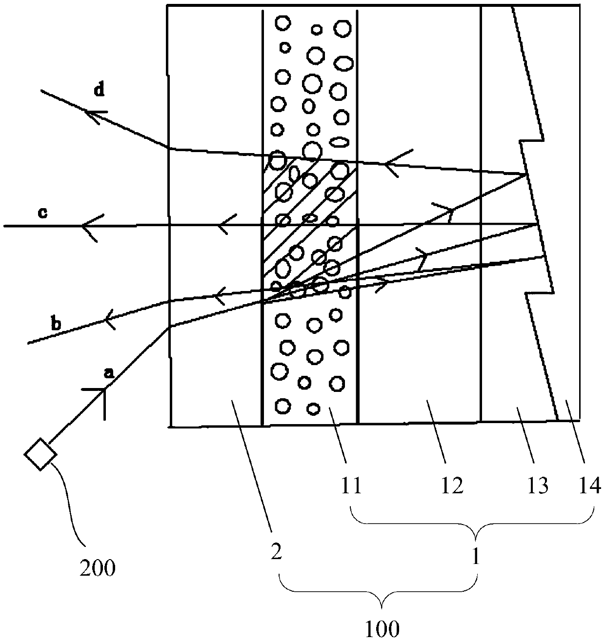
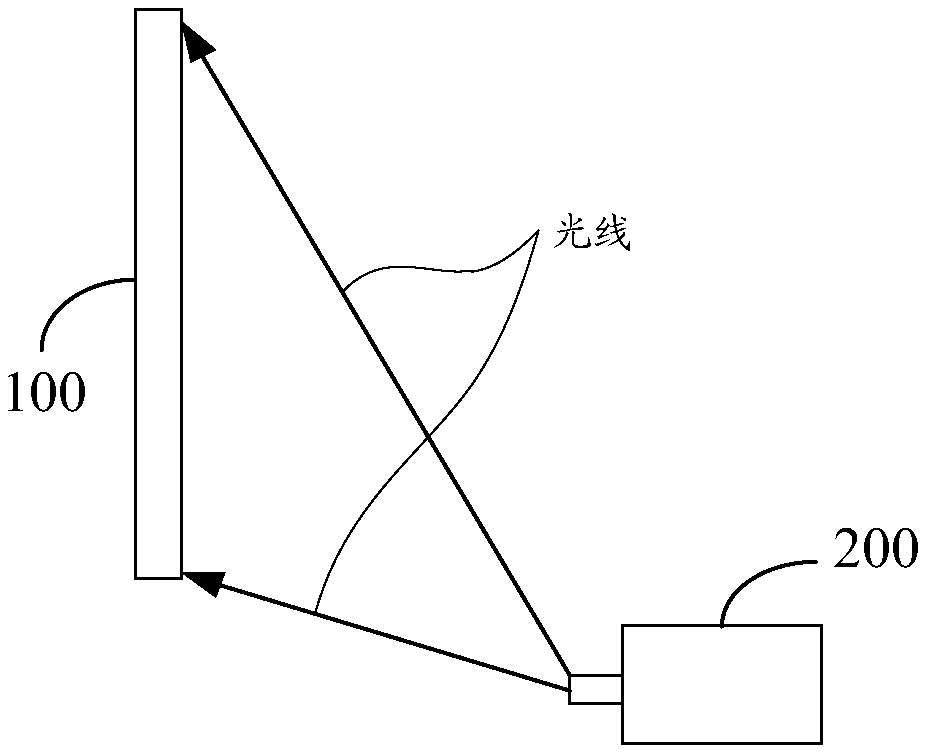
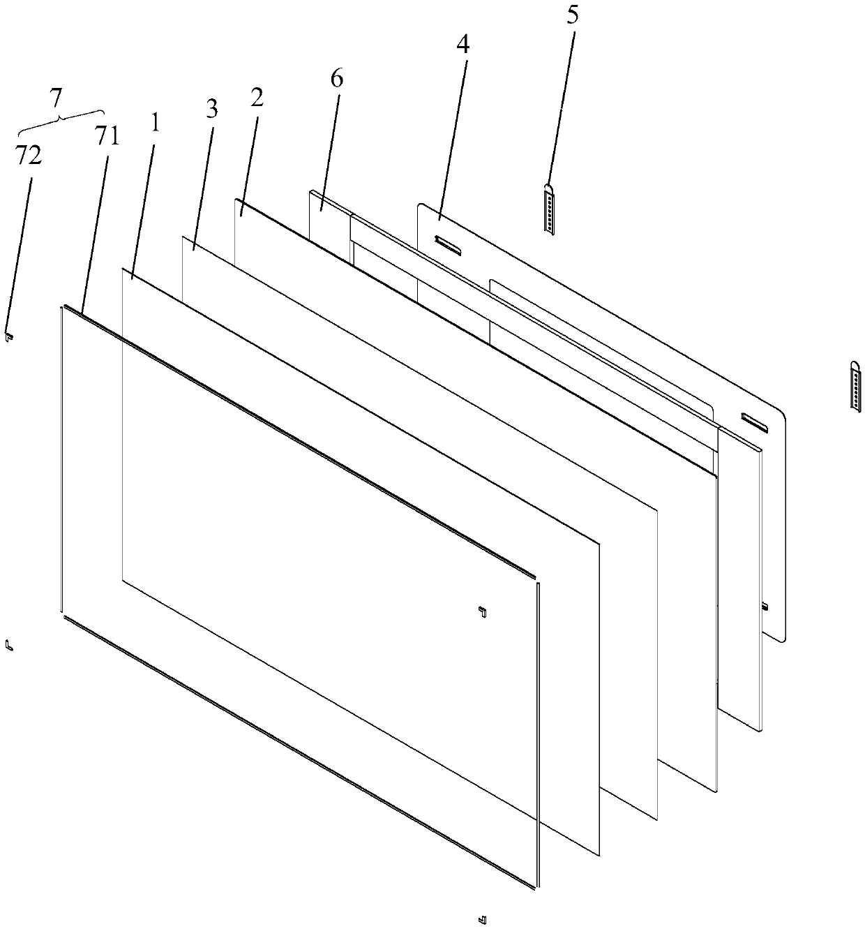
[0059] Based on the above problems, the embodiment of the present invention provides a projection screen 100, please refer to Figure 1 to Figure 5 , the projection screen 100 includes: an optical film 1, and a supporting backboard 2 arranged on one side of the optical film 1; wherein, the supporting backboard 2 is bonded to the optical film 1, and the supporting backboard 2 ...


PUM

PropertyMeasurementUnit
thicknessaaaaaaaaaa
thicknessaaaaaaaaaa
thicknessaaaaaaaaaa

Abstract

The invention discloses a projection screen, relates to the technical field of display, and is used for improving the image display effect of a laser projection device. The projection screen comprisesan optical film and a supporting back plate arranged on one side of the optical film, wherein the supporting back plate is bonded with the optical film, and the supporting back plate is a toughened glass plate. The projection screen provided by the invention is used for displaying the image generated by the projection device.

Description

technical field [0001] The invention relates to the field of display technology, in particular to a projection screen. Background technique [0002] Because the electromagnetic radiation of the laser projection device is small, the imaging effect is realistic, the projection distance is short, and it is easy to realize large-screen projection, the laser projection device is increasingly becoming an image display device that is popular with users. [0003] In order to ensure that the laser projection device has a better image display effect, in some prior art, the laser projection device is equipped with a projection screen, and the image provided by the laser projection device is projected onto the projection screen. Moreover, in order to reduce the impact of external ambient light on the projected image on the projection screen, so that users can see very clear projected images during the day, the projection screen uses an optical diaphragm, which can transmit light from th...

Claims


Application Information

Patent Timeline
Patent Type & Authority Applications(China)
IPC IPC(8): G03B21/56G03B21/602
CPCG03B21/56G03B21/602
Inventor 李建军陈波
Owner QINGDAO HISENSE LASER DISPLAY CO LTD
Learn More