Post-processing equipment for storage battery pole group

A battery and pole group technology, applied in the field of battery pole group post-processing equipment, can solve problems such as unfavorable separate processing and packaging, and achieve the effects of high degree of automation, good slotting effect, and power output saving.

Inactive Publication Date: 2020-06-26
长兴水木机电有限公司
View PDF0 Cites 2 Cited by
  • Summary
  • Abstract
  • Description
  • Claims
  • Application Information

AI Technical Summary

Problems solved by technology

[0005] The purpose of the present invention is to address the deficiencies of the prior art, by setting the first clamping assembly to cooperate with the second clamping assembly to complete the one-to-one pole group entry work, and driving the discharge assembly through the pusher assembly, so that the completion After entering the tank, the batter

Method used


Image

  • Post-processing equipment for storage battery pole group
  • Post-processing equipment for storage battery pole group
  • Post-processing equipment for storage battery pole group

Examples


Embodiment 1

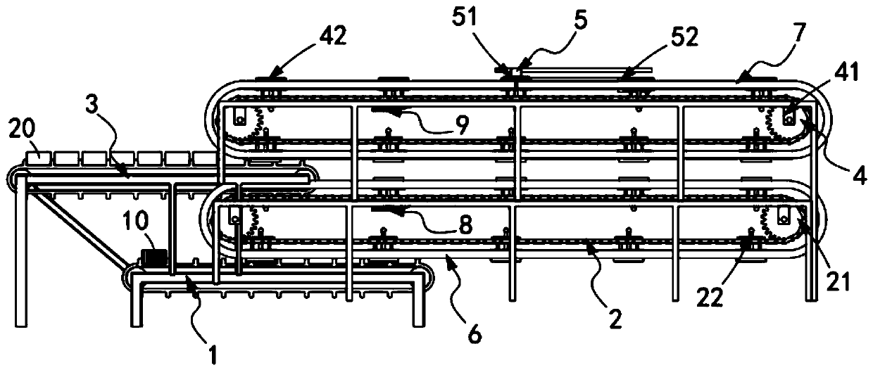
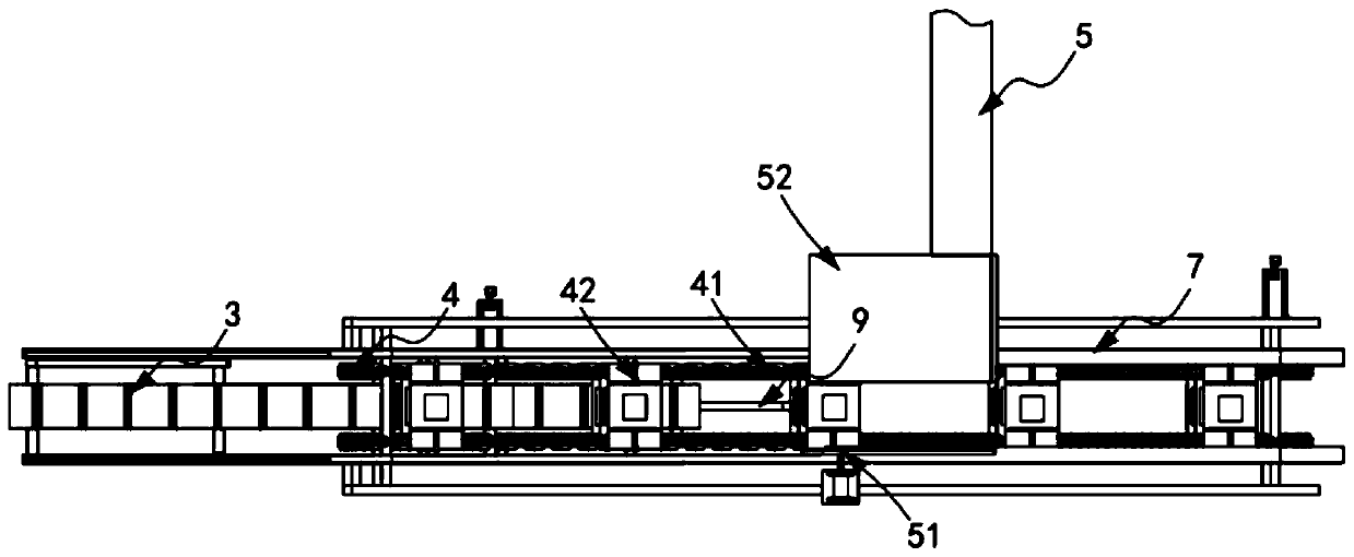
[0056] Such as figure 1 , figure 2 As shown, a battery pole group post-processing equipment includes:

[0057] The pole group transmission mechanism 1, the pole group transmission mechanism 1 is used to sequentially transport several groups of pole groups 10 backward;

[0058] The pole group clamping mechanism 2, the pole group clamping mechanism 2 is located above the pole group transmission mechanism 1, and it includes a first transmission assembly 21 and a number of equidistant along the transmission direction of the first transmission assembly 21. A first tightening component 22 assembled and installed on the first conveying component 21;

[0059] A shell transmission mechanism 3, which is located above the pole group clamping mechanism 2, and is used to sequentially transport several groups of battery shells 20 backwards;

[0060] The shell clamping mechanism 4, the shell clamping mechanism 4 is located above the shell transmission mechanism 3, it includes a second tr...

Embodiment 2

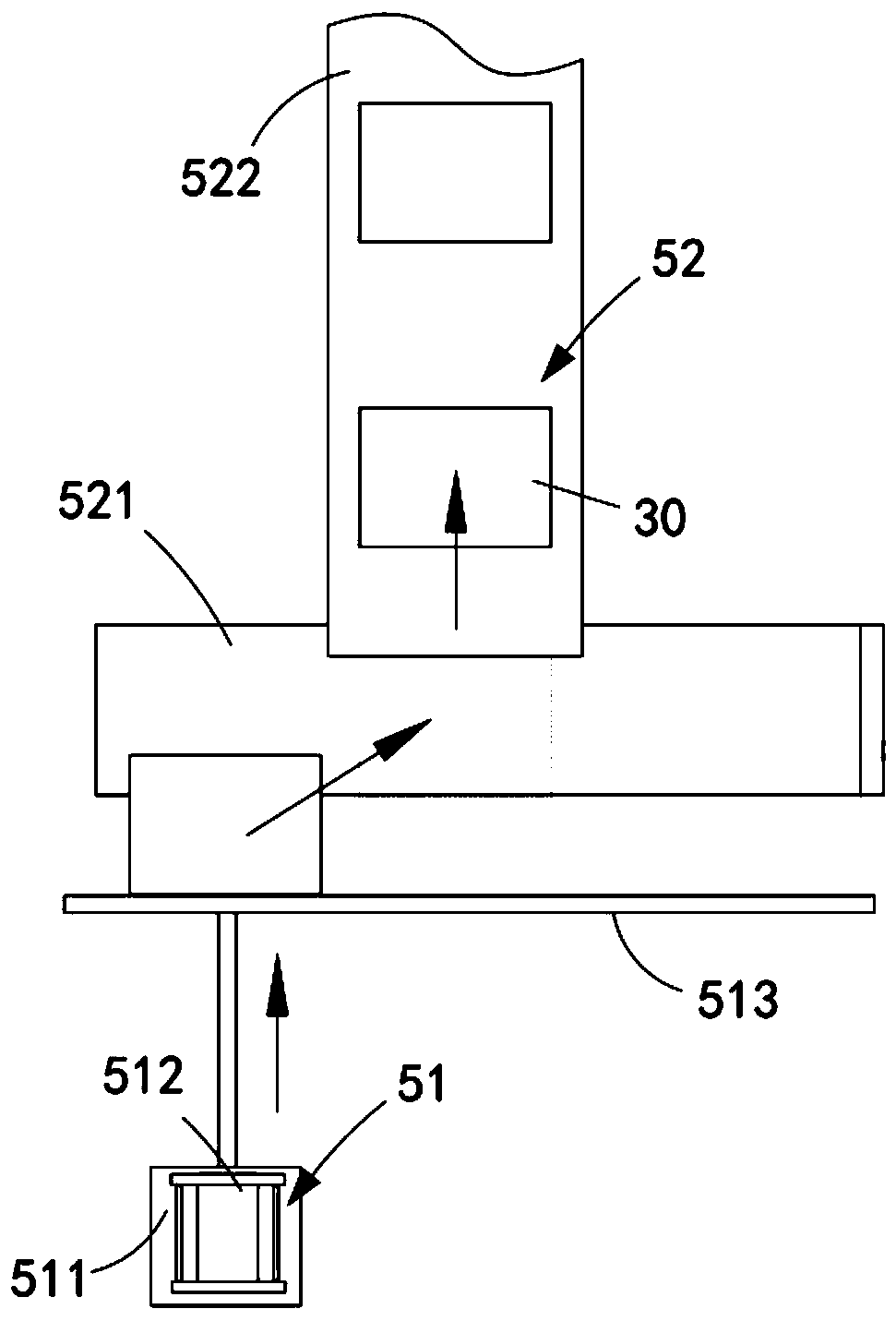
[0087] Such as Figure 4 , Figure 5 and Figure 6 As shown, the components that are the same as or corresponding to those in the first embodiment are marked with the corresponding reference numerals in the first embodiment. For the sake of simplicity, only the differences from the first embodiment will be described below. The difference between this embodiment two and embodiment one is:

[0088] further, such as Figure 4 , Figure 5 and Figure 6 As shown, the first tightening assembly 22 and the second tightening assembly 42 both include:

[0089] Base 221, the base 221 is installed on the sprocket chain unit 212 and the sliding seat 81 is vertically slidably arranged on the base 221, the lower end of the base 221 is provided with a support rod 222, the two sides of the base 221 A support rod 222 is arranged on the side, and the end of the support rod 222 is slidably arranged in the limit groove on the machine tool 211. The installation plate 83 is fixedly connected wit...


PUM


Abstract

The invention relates to post-processing equipment for a storage battery pole group. The post-processing equipment comprises a pole group conveying mechanism, a pole group clamping mechanism, a shellconveying mechanism, a shell clamping mechanism, and a battery output mechanism. A first guide assembly controls a first hooping assembly to clamp a pole group in a conveying state and convey the polegroup backwards. A second guide assembly controls a second hooping assembly to clamp a storage battery shell in the conveying state and convey the storage battery shell backwards. A third guide assembly lifts the first hooping assembly and inserts the first hooping assembly into the storage battery shell clamped by the correspondingly arranged second hooping assembly. A fourth guide assembly is used for jacking the second hooping assembly to the output end of a pushing assembly, and the pushing assembly is used for pushing the jacked storage battery to a discharging assembly. The technical problem that during groove entering for work, grouped pressing and batched output are needed, and batched interval output is conducted at the same time, which do not facilitate later one-to-one separated machining and packaging is solved.

Description

technical field [0001] The invention relates to the technical field of battery pole groups, in particular to post-processing equipment for battery pole groups. Background technique [0002] Large-density storage battery is a large-scale backup power supply used in communication, electric power, UPS and other fields. Because of its large size and heavy weight, its production process is more special, especially for the extremely group lower tank of large-density storage battery. Difficulties for manufacturers. At present, domestic manufacturers of large-density storage batteries mainly use two kinds of manual troughs and machine troughs. [0003] The patent document with the patent number CN2016209744327 discloses a lead-acid storage tank entry device, which belongs to the technical field of large-scale lead storage battery production. There is a pressure plate driven by a cylinder that can move vertically downwards above the two trough areas, and the bottom surface of one o...

Claims


Application Information

Patent Timeline
IPC IPC(8): H01M4/16H01M4/14H01M10/04
CPCH01M4/14H01M4/16H01M10/0404Y02E60/10Y02P70/50
Inventor 周杰钱俊
Owner 长兴水木机电有限公司
Why Eureka
Try Eureka