Waterproof, moistureproof and sand-proof power distribution cabinet through utilizing fluid energy

A technology of fluid energy and power distribution cabinets, which is applied in substation/power distribution device enclosures, electrical components, substation/switch layout details, etc., can solve problems such as difficult implementation, complex structure, high cost, etc. The effect of increasing the speed and increasing the waterproof radius

Active Publication Date: 2020-06-26
SHANDONG ZHUOLI ELECTRIC APPLIANCE CO LTD
View PDF4 Cites 2 Cited by
  • Summary
  • Abstract
  • Description
  • Claims
  • Application Information

AI Technical Summary

Problems solved by technology

[0005] The purpose of the present invention is to solve the problems of complicated structure, high cost, poor effect and difficult implementation caused by the waterproof, moisture-proof and sand-proof of the existing outdoor power distribution cabinets, and proposes a waterproof, moisture-proof and sand-proof system using fluid energy. Power distribution cabinet

Method used


Image

  • Waterproof, moistureproof and sand-proof power distribution cabinet through utilizing fluid energy
  • Waterproof, moistureproof and sand-proof power distribution cabinet through utilizing fluid energy
  • Waterproof, moistureproof and sand-proof power distribution cabinet through utilizing fluid energy

Examples


Embodiment 1

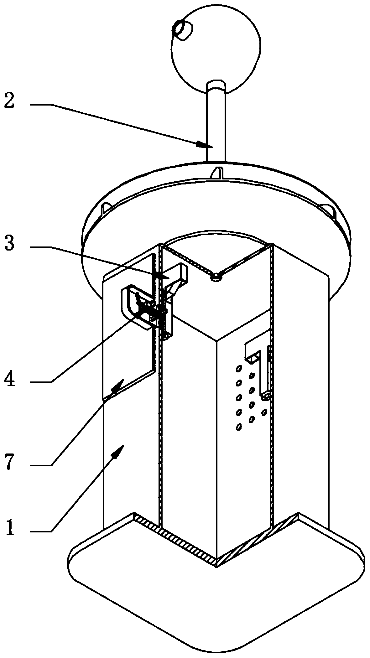
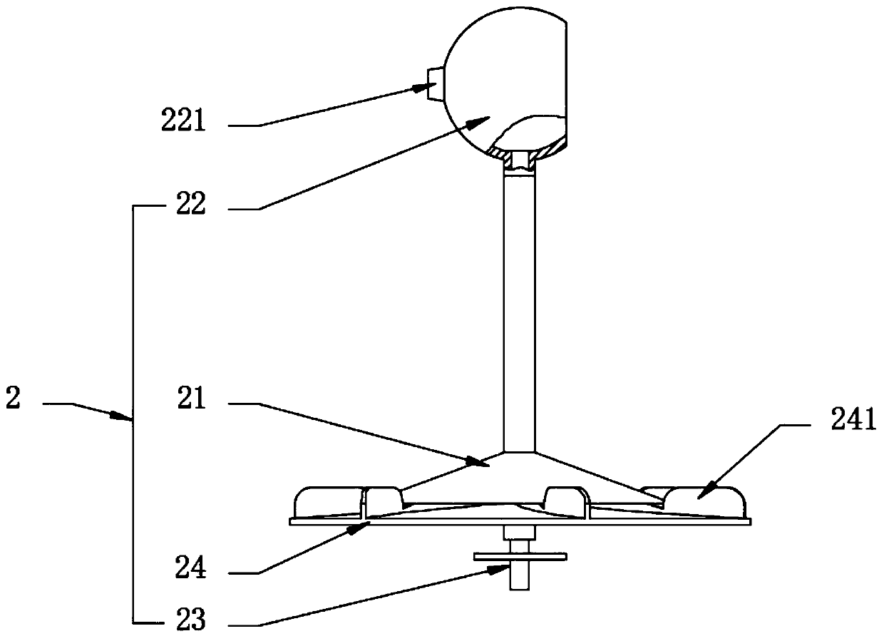
[0040] see Figure 1-8, a waterproof, moisture-proof and sand-proof power distribution cabinet utilizing fluid energy, comprising a cabinet box 1, a fluid energy waterproof device 2 located on the top of the cabinet box 1, a moisture-proof cover plate 7 located on the side wall of the cabinet box 1, and a moisture-proof cover plate located on the side wall of the cabinet box 1 Inside the fluid-distributing drive device 3 and the moisture-proof mechanism 4, the moisture-proof mechanism 4 is fixedly installed on the side wall of the cabinet box 1 and one end is connected to the inside of the moisture-proof cover plate 7, and the other end cooperates with the fluid-distributing drive device 3, and the fluid energy waterproof device 2 It includes a conical cover 21 for converging flow, a drainage housing 22 located at the top of conical cover 21 for converging flow and connected through a drainage tube, a diversion tube 23 located at the bottom of conical conical cover 21 for conve...

Embodiment 2

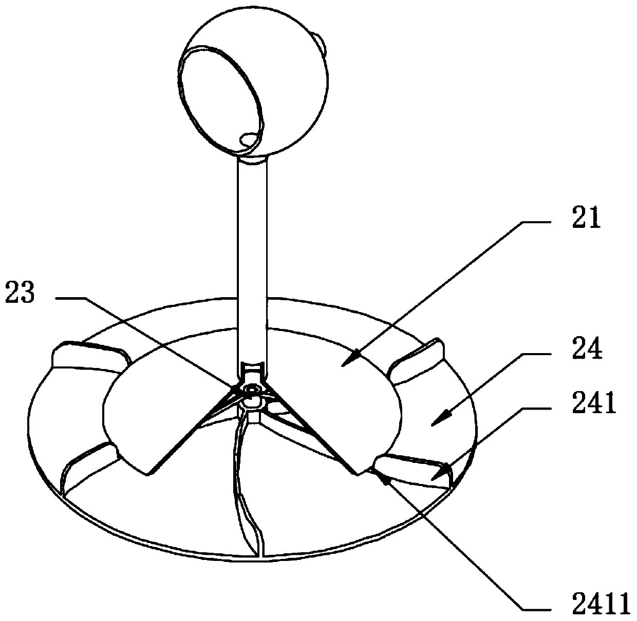
[0042] see image 3 In a further description relative to Embodiment 1, the upper end surface of the arc-shaped blade 241 and the lower part of the edge position of the conical cover 21 is provided with a pit 2411, and the edge position of the conical cover 21 sinks into the pit 2411, This can reduce the gap with the turntable 24, and then can increase the speed of the airflow through the gap, and then increase the rotation speed of the turntable 24, which has the effect of increasing the rotation speed, thereby increasing the centrifugal force and waterproof radius of rainwater.

Embodiment 3

[0044] see Figure 6 and Figure 8 , and the difference of Embodiment 1 is that one end of the positioning sleeve 413 is also equipped with a driving motor 5, and the output shaft of the driving motor 5 is fixedly connected with the rotating shaft 43. Since the overall structure of the moisture-proof mechanism 4 is ingeniously designed and does not occupy a volume, the driving motor 5. Connect the external control circuit. The control circuit involves wind speed sensor, humidity sensor and corresponding single-chip microcomputer, which is convenient to control the start of the drive motor 5 according to the wind speed; by setting the drive motor 5, the rotating shaft 43 can be driven to rotate, so that the moisture-proof cover plate 7 can close the cabinet 1 side wall, this situation is suitable for windy and sandy weather, because there are a lot of sand or impurities in windy weather, it is easy to enter the cabinet 1 through the cooling holes, and then damage the electrical...


PUM


Abstract

The invention discloses a waterproof, moistureproof and sand-proof power distribution cabinet through utilizing the fluid energy. The power distribution cabinet comprises a cabinet box, a fluid energywaterproof device located at the top of the cabinet box, a moistureproof cover plate located on the side wall of the cabinet box, a shunt body driving device located in the cabinet box and a moistureproof mechanism. In the present invention, a fluid energy waterproof device is arranged at the top of a cabinet box; wind energy of strong wind and rain can be collected and converted into centrifugalenergy through the rotating disc on the fluid energy waterproof device, and the waterproof area can be increased through cooperation with high-speed airflow exhausted to the periphery from the upperportion of the rotating disc. A shunt body driving device is arranged in a cabinet box; a flow guide pipe arranged on the fluid energy waterproof device can be used for collecting rainwater and guiding the rainwater into a water storage tank arranged on the flow division body driving device; the water storage tank slides downwards to convert kinetic energy of the rack arranged on the lower portionof the water storage tank by means of dead weight, sealing and damp proofing of the cabinet box are achieved by arranging the damp-proof mechanism and the damp-proof cover plate, the waterproof and damp-proof structure of the cabinet box is achieved by means of wind and rain energy, the energy-saving effect is good, and the automatic control function is achieved.

Description

technical field [0001] The invention relates to the field of electric power technology, in particular to a waterproof, moisture-proof and sand-proof power distribution cabinet utilizing fluid energy. Background technique [0002] The interior of the power distribution cabinet is mainly used to install various electrical equipment. The heat dissipation of the power distribution cabinet needs to be guaranteed. Usually, a large number of cooling holes are opened on the side wall of the power distribution cabinet for heat dissipation. [0003] At present, in areas where heavy wind and rain frequently occur, such power distribution cabinets with a large number of cooling holes have poor moisture-proof effect. Specifically, in heavy wind and rain, water vapor easily enters the inside of the cabinet through the cooling holes under the action of airflow. In turn, it is easy to cause the power components inside the cabinet to be damp and cause short circuit hazards. In windy and sand...

Claims


Application Information

Patent Timeline
Patent Type & Authority Applications(China)
IPC IPC(8): H02B1/56H02B1/28H02B1/46H02B1/48
CPCH02B1/28H02B1/46H02B1/48H02B1/565
Inventor 朱凯凯
Owner SHANDONG ZHUOLI ELECTRIC APPLIANCE CO LTD
Why Eureka
Try Eureka