New material stirring device capable of mixing materials more uniformly and realizing automatically changing

A technology of stirring device and new material, which is applied to mixers with rotary stirring devices, mixers, transportation and packaging, etc., can solve the problems of changing the characteristics of new materials, affecting production efficiency, and insufficiently uniform mixing, so as to improve production. quality, improve mixing efficiency, and ensure the effect of uniformity

Inactive Publication Date: 2020-06-30
杭州酿蜜科技有限公司
0 Cites 6 Cited by

AI-Extracted Technical Summary

Problems solved by technology

[0003] During the use of the current stirring device, it often occurs that the mixing is not uniform enough. This is mainly because the length of the stirring rod is fixed, so the stirring diameter will not change, which leads to the mater...

Method used

The material of turning block 10 is steel material and the size of turning block 10 is less than the length of motor, turning block 10 is connected with rotating bar 3 by gear set, and the material of slide block 12 is steel material, and turning block 10 The outer side is provided with a turning groove 11, the turning groove 11 is a cross thread groove, the inner wall of the turning groove 11 is movably connected with a slider 12, the slider 12 plays the role of transmission, and the right side of the slider 12 is fixedly connected with the mounting seat 9. The slide bar 13 that is...

Abstract

The invention discloses a new material stirring device capable of mixing materials more uniformly and realizing automatically changing, and belongs to the technical field of new materials. The devicecomprises a tank body, the top of the tank body is fixedly connected with a motor; a rotating rod fixedly connected with an output shaft of the motor is movably connected to the middle of the tank body, an electromagnet is fixedly connected to the middle of the rotating rod, uniformly distributed fixed rods are fixedly connected to the outer side of the rotating rod, springs are fixedly connectedto the inner walls of the fixed rods, movable rods are fixedly connected to the outer sides of the springs, and magnetic blocks are fixedly connected to the middles of the movable rods. The inventiondiscloses the new material stirring device capable of mixing materials more uniformly and automatically changing. Through cooperative use of the movable rods and the electromagnet, during use, the movable rods can do telescopic motion in the fixed rod at a constant speed, so that the stirring radius of the stirring device is continuously changed, it is guaranteed that materials cannot be accumulated, the mixing efficiency of the materials is improved, the uniformity of the materials is guaranteed, and the performance of new materials is guaranteed.

Application Domain

Technology Topic

Image

  • New material stirring device capable of mixing materials more uniformly and realizing automatically changing
  • New material stirring device capable of mixing materials more uniformly and realizing automatically changing
  • New material stirring device capable of mixing materials more uniformly and realizing automatically changing

Examples

  • Experimental program(1)

Example Embodiment

[0021] The technical solutions in the embodiments of the present invention will be clearly and completely described below in conjunction with the accompanying drawings in the embodiments of the present invention. Obviously, the described embodiments are only a part of the embodiments of the present invention, rather than all the embodiments. Based on the embodiments of the present invention, all other embodiments obtained by those of ordinary skill in the art without creative work shall fall within the protection scope of the present invention.
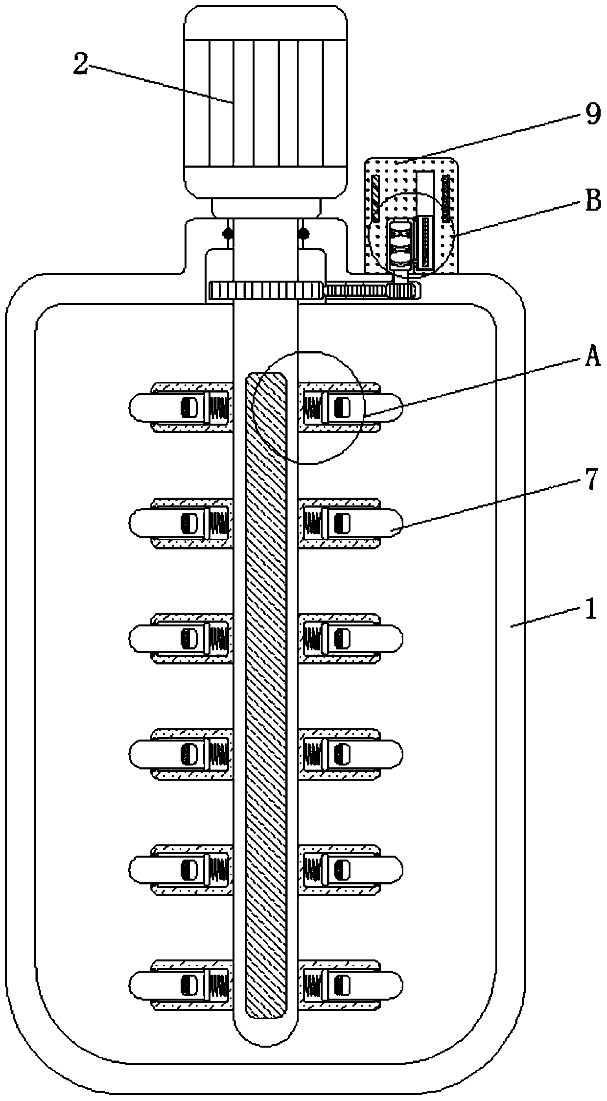
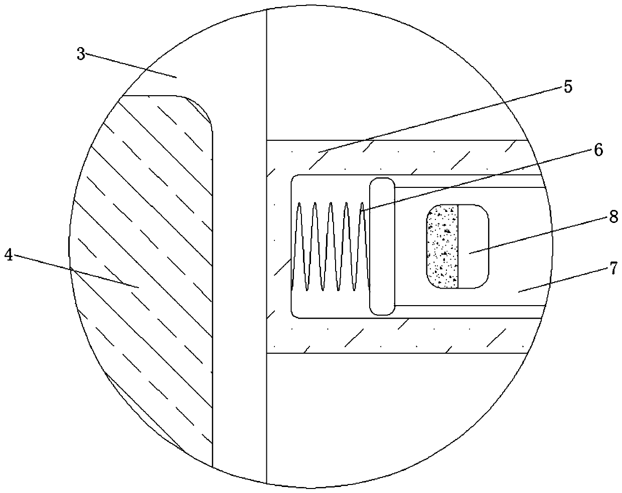
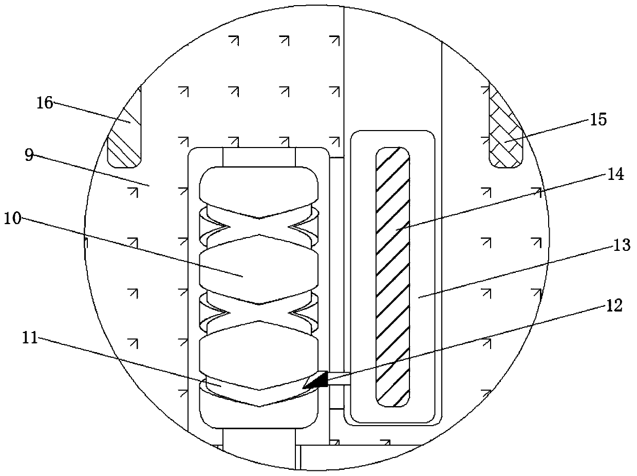
[0022] See Figure 1-6 , A new material stirring device with more uniform mixing and automatic change, including a tank body 1. The tank body 1 plays a role of holding various raw materials. The material of the tank body 1 is a steel material and the shape of the tank body 1 is Cylindrical, the model of motor 2 is 6312B14, the number of poles is 2 poles, the rated power is 0.18KW, the rated voltage is 220/380V, the top of the tank 1 is fixedly connected with the motor 2, and the motor 2 functions as a power source , The middle of the tank 1 is movably connected with a rotating rod 3 fixedly connected with the output shaft of the motor 2. The rotating rod 3 plays a role of transmission. The material of the rotating rod 3 is a high-hardness non-magnetic material and the length of the rotating rod 3 is smaller than that of the tank. The height of the body 1, the magnetic size of the electromagnet 4 can be changed with the circuit voltage, the greater the circuit voltage, the greater the magnetism of the electromagnet 4, and the magnetism outside the electromagnet 4 is the same as the magnetism inside the magnet block 8. An electromagnet 4 is fixedly connected to the middle of the, and the electromagnet 4 plays a transmission role.
[0023] The outer side of the rotating rod 3 is fixedly connected with fixed rods 5 evenly distributed. The fixed rods 5 play a role in restricting the moving direction of the movable rod 7. The material of the fixed rod 5 is hard non-magnetic material and the number of the fixed rods 5 is twelve. One, the spring 6 is a tension spring, the material of the movable rod 7 is a hard non-magnetic material and the length of the movable rod 7 is less than the length of the fixed rod 5. The inner wall of the fixed rod 5 is fixedly connected with the spring 6, and the spring 6 serves to The movable rod 7 is retracted into the fixed rod 5. The outside of the spring 6 is fixedly connected with a movable rod 7, and the movable rod 7 plays a role in changing the stirring diameter. The middle of the movable rod 7 is fixedly connected with a magnetic block 8, which acts as a magnetic block. To the effect of transmission, the material of the magnetic block 8 is rubidium magnet material and the size of the magnetic block 8 is smaller than the size of the movable rod 7, the material of the mounting seat 9 is steel material and the shape of the mounting seat 9 is rectangular parallelepiped. The top and the right side of the motor 2 are fixedly connected with a mounting seat 9, which facilitates installation. The middle part of the mounting seat 9 is rotatably connected with a rotating block 10 connected to the middle of the rotating rod 3, and the rotating block 10 functions To the role of transmission.
[0024] The material of the rotating block 10 is made of steel and the size of the rotating block 10 is smaller than the length of the motor. The rotating block 10 is rotatably connected with the rotating rod 3 through a gear set. The material of the slider 12 is made of steel. The outer side of the rotating block 10 is provided with Rotary groove 11, the rotary groove 11 is a cross thread groove, the inner wall of the rotary groove 11 is movably connected with a sliding block 12, the sliding block 12 plays a transmission role, the right side of the sliding block 12 is fixedly connected with the inner wall of the mounting seat 9 movably connected The middle part of the sliding rod 13 is fixedly connected to the dielectric plate 14. The dielectric plate 14 functions to change the relative area of ​​the positive plate 15 and the negative plate 16, and changes the circuit voltage. The inner wall of the mounting seat 9 is close to A positive electrode plate 15 is fixedly connected to the left side of the rotating block 10, and a negative electrode plate 16 electrically connected to the electromagnet 4 is fixedly connected to the inner wall of the mounting base 9 and to the right side of the sliding rod 13.
[0025] Working principle: In the initial state, such as figure 1 As shown, the movable rod 7 is contracted into the fixed rod 5 under the action of the spring 6 and the electromagnet 4 is in a power-off state. The stirring radius of the stirring device is equal to the length of the fixed rod 5.
[0026] When the stirring device is working, both the motor 2 and the electromagnet 4 are energized. Since the magnetism outside the electromagnet 4 is the same as the magnetism inside the magnet block 8, the magnet block 8 will drive the movable rod 7 to move outward together and move At the same time, the rod 7 is guaranteed to be fixed in position under the pulling force of the spring 6. At the same time, the rotation of the rotating rod 3 will drive the rotating block 10 to rotate. At this time, the rotating block 10 will drive the slider 13 to move up and down through the slider 12, and the dielectric in the slider 13 The plate 14 will constantly change the relative area of ​​the positive plate 15 and the negative plate 16, thereby increasing or decreasing the circuit voltage. At this time, the magnetic size of the electromagnet 4 will also change constantly, and the force received by the magnetic block 8 will also change, resulting in The protruding length of the movable rod 7 is continuously changed, thereby achieving the effect of changing the stirring diameter and effectively improving the mixing effect of the materials.
[0027] Although the embodiments of the present invention have been shown and described, those of ordinary skill in the art can understand that various changes, modifications, and substitutions can be made to these embodiments without departing from the principle and spirit of the present invention. And variations, the scope of the present invention is defined by the appended claims and their equivalents.

PUM

no PUM

Description & Claims & Application Information

We can also present the details of the Description, Claims and Application information to help users get a comprehensive understanding of the technical details of the patent, such as background art, summary of invention, brief description of drawings, description of embodiments, and other original content. On the other hand, users can also determine the specific scope of protection of the technology through the list of claims; as well as understand the changes in the life cycle of the technology with the presentation of the patent timeline. Login to view more.

Similar technology patents

Classification and recommendation of technical efficacy words

  • Guaranteed uniformity
  • Improve mixing efficiency

Visual soil freeze-thawing process test apparatus

Owner:NORTHWEST INST OF ECO-ENVIRONMENT & RESOURCES CAS
Why Eureka
Try Eureka