On-site automatic welding device and welding method for large pipelines

An automatic welding, on-site technology, applied in auxiliary devices, welding equipment, welding equipment and other directions, can solve the problems of reducing the safety factor, reducing work efficiency, injury to workers, etc., to improve the safety factor, improve the effect of welding, use Safe and convenient effect

Inactive Publication Date: 2020-06-30
林进卓
View PDF9 Cites 8 Cited by
  • Summary
  • Abstract
  • Description
  • Claims
  • Application Information

AI Technical Summary

Problems solved by technology

[0004] The present invention provides an on-site automatic welding device and welding method for large-scale pipelines, which can effectively solve the problem that when the pipelines are automatically welded outdoors in the above-mentioned background technology, when fixing pipelines with different diameters, it is necessary for the staff to manually weld the pipeline according to the diameter of the pipeline. Adjust the distance between the support wheels to support the pipeline, but manually adjusting the pipeline may easily cause damage to the staff, reduce the safety factor, reduce work efficiency, and increase the working hours. question of strength

Method used


Image

  • On-site automatic welding device and welding method for large pipelines
  • On-site automatic welding device and welding method for large pipelines
  • On-site automatic welding device and welding method for large pipelines

Examples


Embodiment

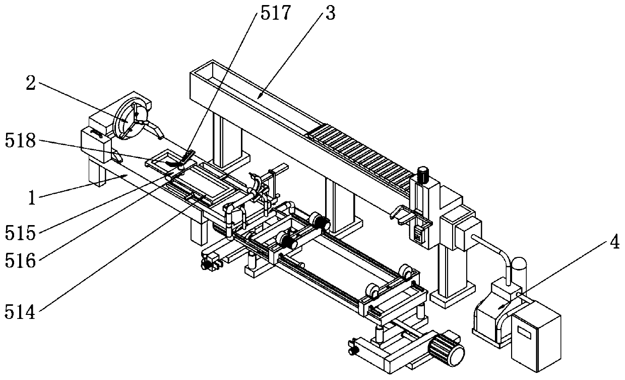
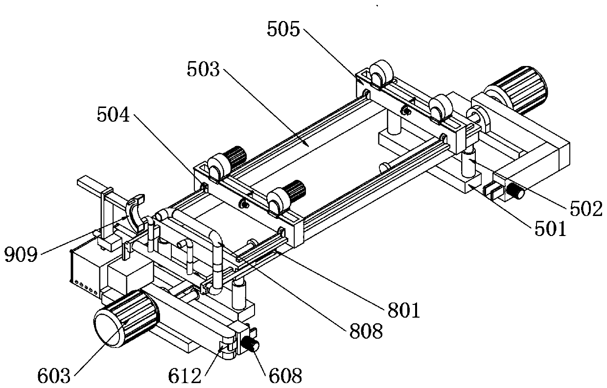
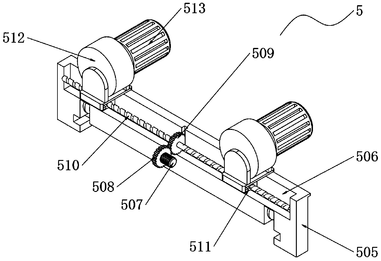
[0047] Example: such as Figure 1-11 As shown, the present invention provides a technical solution, a large pipeline on-site automatic welding device, including a welding support frame 1, a welding positioner 2 is installed on one end of the top surface of the welding support frame 1 through screws, and a welding positioner 2 is placed on one side of the welding support frame 1. The mobile support frame 3 is equipped with an automatic welding machine main body 4 at one end of the mobile support frame 3, a support adjustment assembly 5 is placed at one end of the welding support frame 1, and the bottom surfaces of the welding support frame 1, the mobile support frame 3 and the support adjustment assembly 5 are all on the same level. The length and width of one end of the support adjustment assembly 5 are respectively equal to the length and width of one end of the welding support frame 1, which facilitates the alignment of different pipes, facilitates the welding of the pipes, a...


PUM


Abstract

The invention discloses a one-site automatic welding device and welding method for large pipelines. The automatic welding device comprises a welding supporting frame, wherein two horizontal supportingplates are placed on one side of the welding supporting frame, flush electric pushing rods are installed at the two ends of the top surfaces of the two horizontal supporting plates correspondingly, the four flush electric pushing rods are installed at the four corners of the bottom surface of a flush supporting frame correspondingly, material supporting rods are installed in the two ends of the top surface of the flush supporting frame in an embedded mode, supporting rolling wheels are installed at the bottom ends of the material supporting rods, the bottom surfaces of the supporting rollingwheels make contact with the top surface of the flush supporting frame, lead screw installing grooves are formed in the middles of the top surfaces of the material supporting rods, rotating motors areinstalled in the middles of one ends of the material supporting rods, friction wheels are movably installed at the top ends of sliding frames, and a movable supporting plate is installed at one end of the outer side of the fixing supporting frame in an embedded mode. Through the cooperative use of the flush electric pushing rods, an inclined rolling wheel frame, a welding positioner and a corresponding electric pushing rod, the center lines of the two pipelines are located on the same straight line conveniently, the pipelines can be adjusted and supported, and the working efficiency is improved.

Description

technical field [0001] The invention relates to the technical field of pipeline welding, in particular to an automatic welding device and welding method for large-scale pipelines on site. Background technique [0002] In the past 20 years, with the development of digitization, automation, computer and mechanical design technology, and the high emphasis on welding quality, automatic welding has developed into an advanced manufacturing technology, and automatic welding equipment has played an important role in the application of various industries The role is getting bigger and bigger, and the scope of application is expanding rapidly. In modern industrial production, the mechanization and automation of the welding production process is an inevitable trend in the modernization of the welding mechanism manufacturing industry. [0003] When automatically welding pipes outdoors, when fixing pipes with different diameters, the staff needs to manually adjust the distance between th...

Claims


Application Information

Patent Timeline
Patent Type & Authority Applications(China)
IPC IPC(8): B23K37/053B23K37/00B23K31/02
CPCB23K31/027B23K37/00B23K37/003B23K37/053B23K37/0538
Inventor 林进卓
Owner 林进卓
Why Eureka
Try Eureka