High-steepness optical mirror surface error polishing correction processing method

A technology of optical mirror surface and processing method, applied in optical surface grinder, metal processing equipment, grinding/polishing equipment, etc., can solve the problem of reducing processing accuracy, achieve the effect of reducing processing cost and solving the problem of high-efficiency and high-precision processing

Active Publication Date: 2020-06-30
NANJING ZHONGKE ASTROMOMICAL INSTR
View PDF11 Cites 6 Cited by
  • Summary
  • Abstract
  • Description
  • Claims
  • Application Information

AI Technical Summary

Problems solved by technology

[0004] However, the limitations of linear forming theory in the processing of complex curved surfaces such as aspheric surfaces are becoming more and more obvious. The relationship between material removal and process parameters in the polishing process is described in a linear form, ignoring the nonlinear factors of contact state changes and surface steepness. The non-linear projection of the degree change and the distance between two points on the surface in the Cartesian coordinate system ignores the influence of complex surface geometry that cannot be expanded, which reduces the machining accuracy

Method used


Image

  • High-steepness optical mirror surface error polishing correction processing method
  • High-steepness optical mirror surface error polishing correction processing method
  • High-steepness optical mirror surface error polishing correction processing method

Examples


Embodiment Construction

[0050] The present invention will be described in further detail below in conjunction with the accompanying drawings.

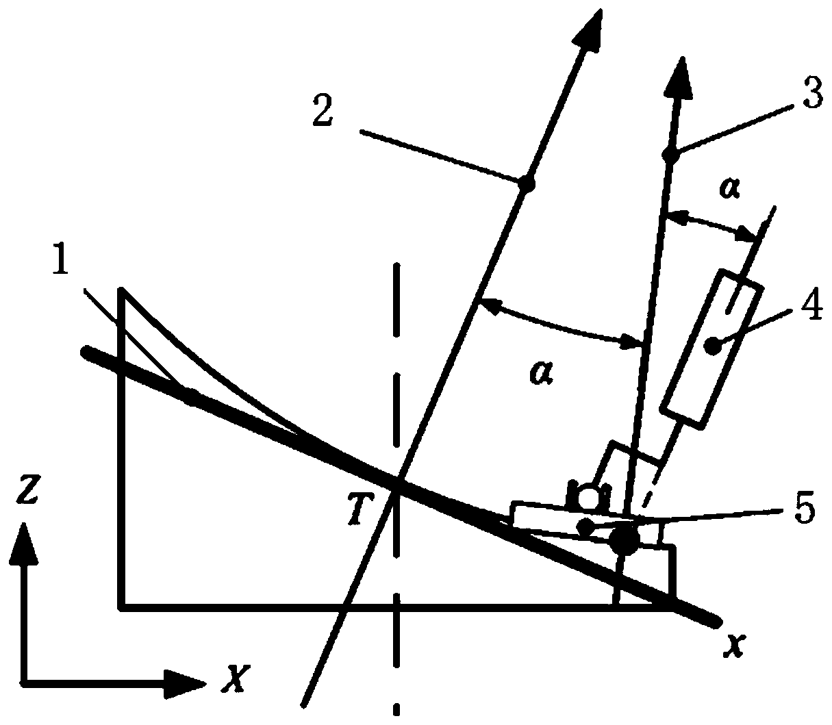
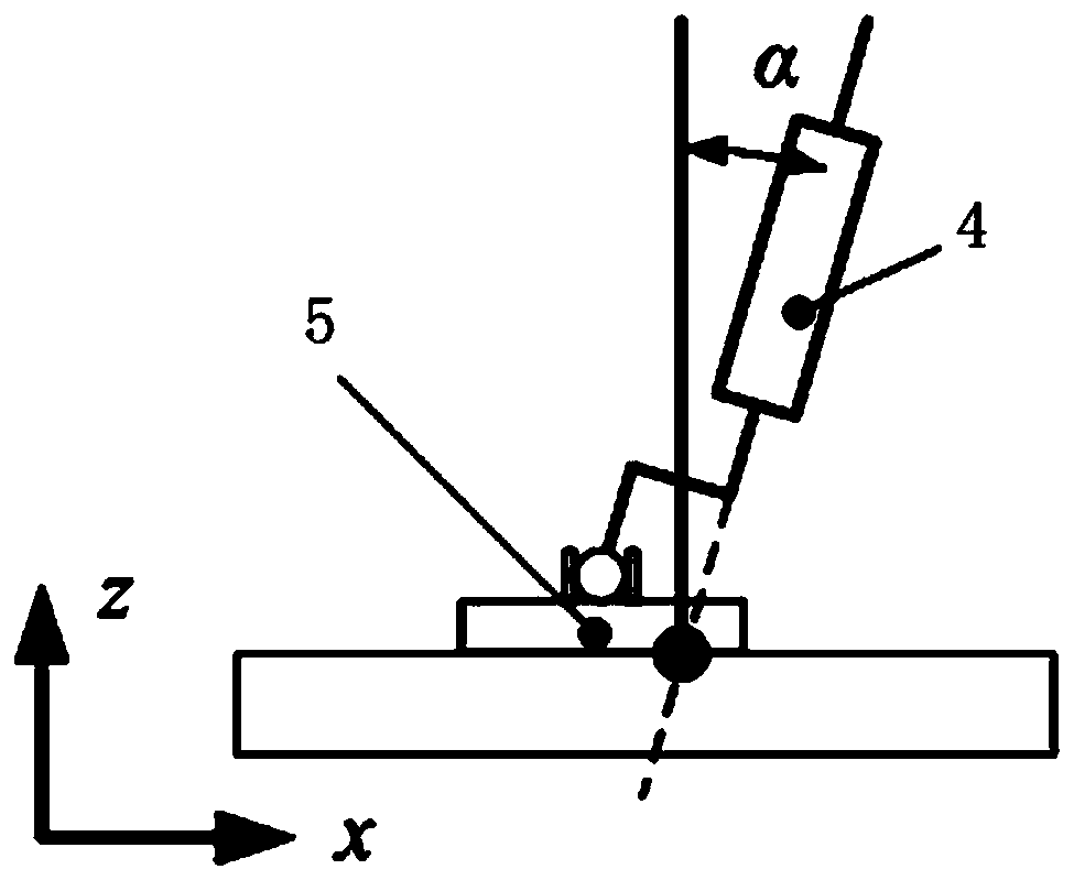
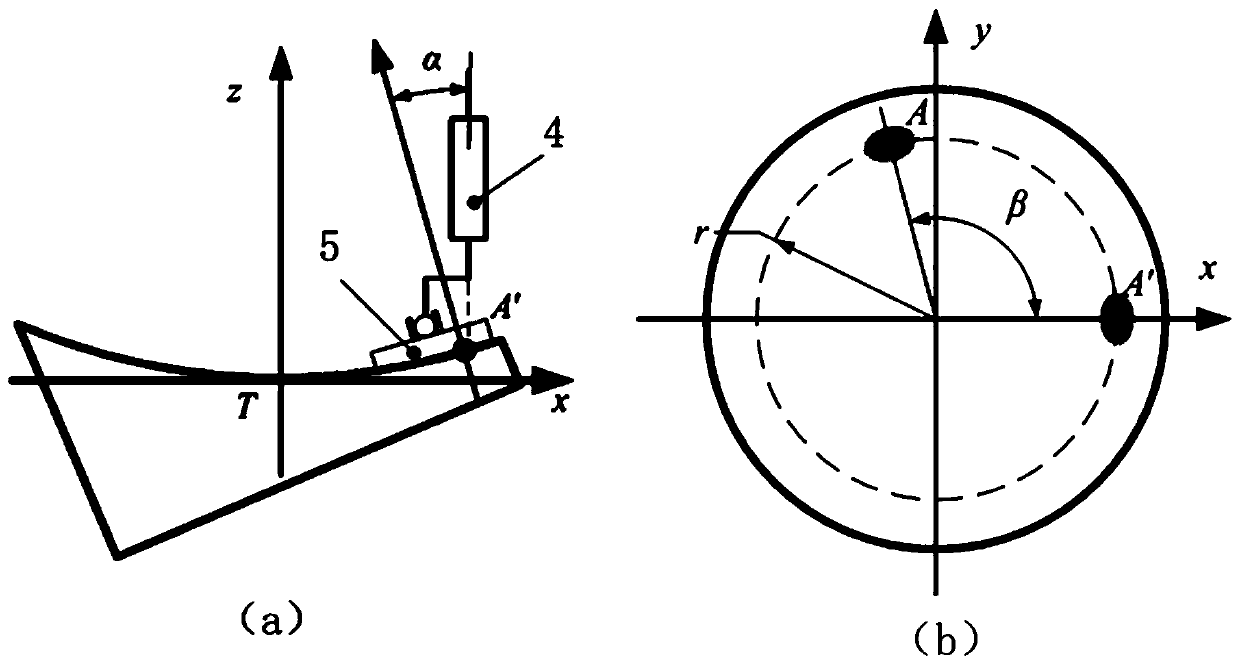
[0051] Such as figure 1 , the processing system includes the closest plane 1, the closest plane normal direction 2, the processing point normal direction 3, the elastic elastic element 4, and the grinding disc 5; the optical mirror structure to be processed in the embodiment of the present invention is as follows Figure 5 As shown, including the closest plane normal direction 2 and the mother mirror axis 6. This embodiment is based on the CCOS forming principle, projecting the high-steep aspheric surface into its closest plane, transforming the tilt removal function to obtain the removal function at any processing position, and then Close to the plane, the high-steep shaping process is described by the matrix multiplication model, and finally the deconvolution algorithm is used to calculate the dwell time and then the speed is used to realize the processing...


PUM


Abstract

The invention discloses a high-steepness optical mirror surface error polishing correction processing method. The high-steepness optical mirror surface error polishing correction processing method comprises the following steps that a high-steepness aspheric surface is projected into a closest plane of the high-steepness aspheric surface on the basis of the CCOS forming principle, transformation processing is conducted on an inclined removal function to obtain a removal function at any processing position, then in the closest plane of the high-steepness aspheric surface, a high-steepness modification process is described by using a matrix multiplication model, and finally the residence time is calculated by using a deconvolution algorithm and then processing is realized by using a speed mode. According to the high-steepness optical mirror surface error polishing correction processing method, the influence of the change of the included angle between the axial direction of a grinding discand the normal direction of a workpiece at the contact point on the removal function is considered, the concept of a variable removal function is introduced, the removal function and the to-be-processed surface form are projected into the closest plane of the to-be-processed surface form, accordingly a matrix forming model of a global variable removal function is established, the residence time is solved through a residence time solving algorithm, the residence time is calculated in a variable speed mode, and therefore high-precision polishing processing of the high-steepness aspheric surfaceis achieved.

Description

technical field [0001] The invention relates to a high-steep optical mirror surface error correction technology, especially the precision and high-efficiency processing of ring-band splicing, which belongs to the field of optical element processing. Background technique [0002] In order to adapt to the development of space optical technology and meet the needs of high imaging quality, the image quality of modern space cameras is usually close to the diffraction limit, requiring the processing accuracy of optical mirrors to be increased from the original λ / 30RMS to λ / 50RMS (λ=632.8nm) ; With the improvement of performance indicators such as the resolution of the optical system, the aspheric surface has become the main form of the mirror surface of the optical system. Compared with traditional spherical mirrors, the traditional single-axis grinding and polishing process cannot be used for aspheric surface processing. Computer Controlled Optical Surfacing (CCOS, Computer Contr...

Claims


Application Information

Patent Timeline
Patent Type & Authority Applications(China)
IPC IPC(8): B24B1/00B24B13/00
CPCB24B1/00B24B13/00
Inventor 焦长君舒勇张真高飞海陈永超王波宫萌
Owner NANJING ZHONGKE ASTROMOMICAL INSTR
Why Eureka
Try Eureka